From the 1860s to 1940s, many oil wells were pumped by a technology that originates in a sixteenth-century power transmission system used in the mining industry.
One engine operated up to 45 pumps in different locations, each up to a mile away. Power was transmitted by means of wooden rods or steel cables that moved back and forth, snaking through the landscape.
The system was so efficient that an engine used for pumping an oil well could operate a whole cluster of pump jacks. The technology, which still operates in a handful of small oil fields, could also work with renewable energy sources, and shows great potential for efficient small-scale energy use.
Jerker line systems can be used to operate water pumps or sawing machines, to forge iron, to process food or fibres, or to make paper.
From the 1500s onwards, engineers developed mechanical power transmission and distribution systems that became ever more sophisticated: Stangenkunsten. Networks of pivoted, wooden field-rods conveyed power from waterwheels in the valleys to mining machinery in the mountains over distances of up to 4 km, operating pumps and bellows, hoisting ores, and transporting miners up and down shafts.
Steam engines, which started replacing water wheels from the 1860s onwards, were not dependent on the proximity of a stream or river, and could thus be located close to the mine shaft. This eliminated the need for mechanical power transmission. However, the Stangenkunst did not disappear. On the contrary, the technology became even more popular after, rather than before, the invention of the steam engine.
For one, it found a new application in oil production, initially in the United States but later all over the world. It was in the oil industry that the Stangenkunst reached the pinnacle of its development, and became known as the “jerker line system”.
The Canadian Jerker Line System
Right from the start of modern oil production in the late 1850s, the Stangenkunst played an important role. It was first used for pumping oil in Oil Springs, Ontario, Canada. While the oil here was of very good quality, production was marginal. The high cost of operating a steam engine at each was not economically viable. In 1863, only four years after the industry came into production, a solution was found by John Henry Fairbank, who set up a system for the transfer of power from a steam engine to multiple oil pumps.
The method, which became known as the “Canadian Jerker Line System”, was remarkably similar to the Stangenkunsten. Fairbank used wooden rods, which swung back and forth from wooden hangers that were suspended from wooden poles, and connected to wooden pump jacks. He didn’t even bother to apply the more efficient pantograph system developed in the 1590s, but used the original single-rod system. This made sense: it was cheaper to build, and friction was less of a problem since the system aimed at distributing power rather than transferring it long-distance (most oil pumps were within one mile of the central power source).
Subdividing and Distributing Power
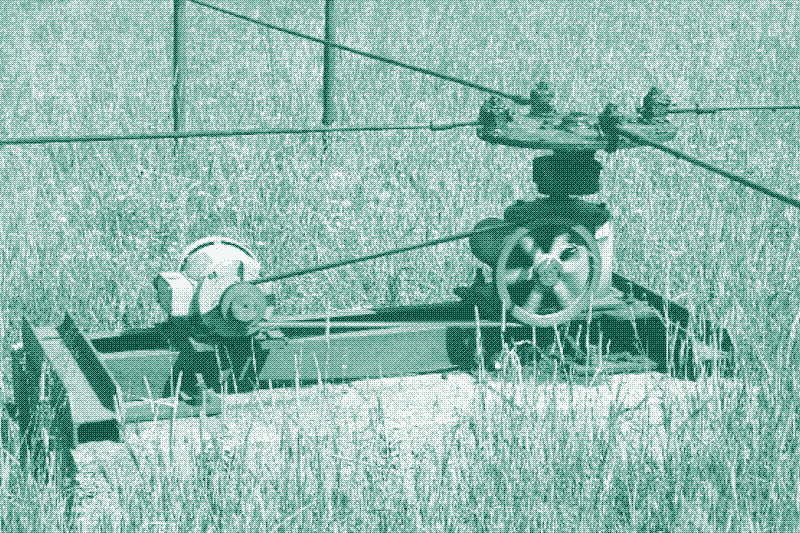
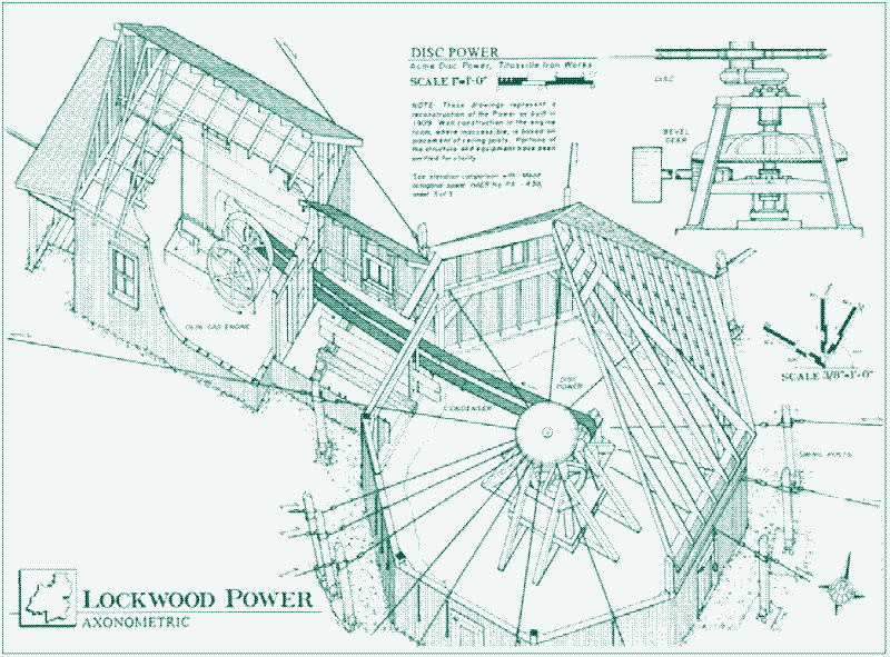
There were some differences between the Fairbank method and the pre-industrial Stangenkunsten. Two cranks converted the circular motion of the steam engine’s wheel to a reciprocating motion that moved two parallel wooden rods back and forth, just as in the older systems powered by water wheels. In Fairbank’s model, however, a mechanism was introduced to slow down the revolution speed of the steam engine. It consisted of a leather belt placed between the wheel of the steam engine and the cranks. Another addition was the bull wheel, a cast-iron wheel making back-and-forth quarter turns. It was housed in a timber frame just outside the engine shed.
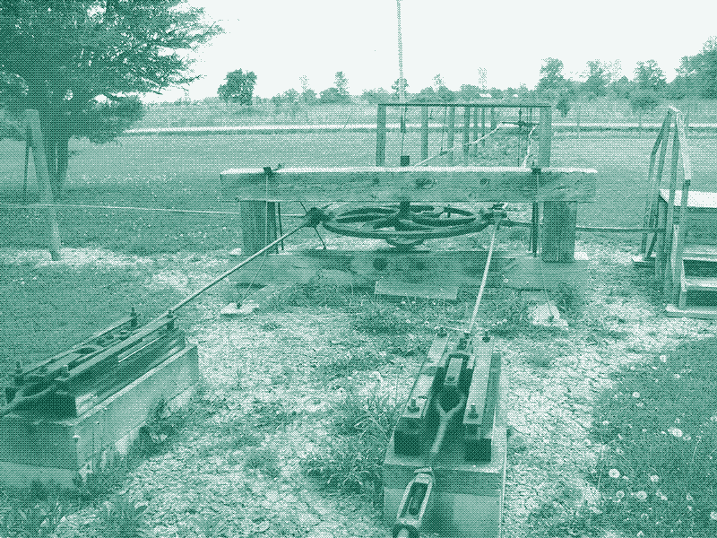
The bull wheel allowed the reciprocating motion of the two cranks to be subdivided over a greater number of rod lines. In the picture above, for instance, power is distributed from the steam engine to the bull wheel via the two wooden rods on the lower left side. It is transferred to a double field line which runs diagonally from upper left to lower right (the main line) while a single rod line extends to the centre and back of the picture. Thus, in this case, five rod lines branch off from the central power instead of one or two.
Additional subdivision of power to other field rods (branch lines) could happen further along the main line, by means of a “field wheel” — a similar cast-iron, oscillating wheel in a timber frame. The field wheel was also used for diverting a main rod line 90 degrees, as can be seen in the picture above. Field wheels replaced the “Kunst Kreuzen” or “Engine Crosses” used in pre-industrial Stangenkunsten.
V-shaped wooden assemblies, lying on their sides, were used to make less sharp turns. The point of the V was anchored, and acted as the pivot for the mechanism. When the jerker line pulled on one leg of the V, the lines comes from the other direction were pulled out, too. A similar V-rod placed upright was used to change direction in the vertical plane when the line crossed a hill or valley.
The Pennsylvania Jerker Line System
The Canadian jerker line system spread to other oilfields but was eventually superseded by a more sophisticated system in which steel cables and iron bars replaced wooden rods. The metal rods were usually called “shackle lines”. This method was developed in 1879 by Pennsylvania oilman Edward Yates and became known as the “Pennsylvania Jerker Line System”.
The famous Pennsylvania oilfields (home to Rockerfeller’s Standard Oil Company) came into production around the same time as the Ontario oil fields. However, unlike in Canada, steam engines were used to power each well for the first two decades. Oil wells in the Allegheny Plateau had a high initial production, which was followed by a rapid drop off. The incentive for pumping these low production wells after their initial outflow was small, as new fields were continually being discovered and drillers would simply sink a new well.
In the late 1870s, following a decline in oil prices and production per well, economising the oil production process became key to profitability. This drive for efficiency resulted in the adoption of the jerker line system, which made using previously-abandoned wells economically viable again.
By 1885, the jerker line system was used widely in Pennsylvania (then the largest oil producer in North America). Thereafter, it spread to other US oil fields. By the early twentieth century, the system was used in oil fields around the world. By then, the technology had improved and numerous oil-well supply companies had developed standardised systems that could be purchased in part or whole.
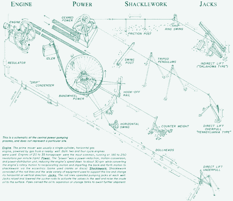
While the Canadian jerker line system was reminiscent of the Stangenkunsten operating in pre-industrial times, the Pennsylvania jerker line system looked radically different. The prime mover (mostly a gas engine supplied from a nearby well) operated a “central power” (either geared or bandwheel) which slowed down the engine speed, converted the engine’s rotary motion to reciprocating motion, and distributed power to all the rod lines.
One Engine Powers 45 pumps
A back-and-forth motion was imparted to the rod lines by an “eccentric”, placed either above or below the geared or bandwheel power, to which 8 to 15 rod lines were hooked that fanned out in all directions. The eccentric was mounted slightly off-center from the power’s central vertical shaft, with the rod lines attached to the outer slip ring. As the eccentric rotated within the slip ring, the slip ring oscillated, pulling the rod lines. For each rotation of the slip ring, the rod lines completed one full stroke (see the illustration below).
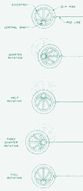
Typically, the mechanism produced 12 to 20 oscillations per minute, pulling the attached shackle lines an equal number of times. Depending on the number of wells, up to three eccentrics could be mounted on the central shaft, so that a total of 45 oil wells in different locations could be pumped. (More commonly, however, 10 to 25 pumps were powered as they wanted to limit the amount of temporarily unproductive wells in case of an engine breakdown.)
Implications for Field Layout
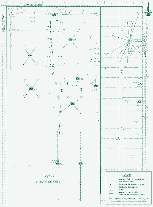
These different approaches to subdividing and distributing power led to distinct field layouts. In the Pennsylvania system, all oil pumps in the cluster were directly connected to the central power via jerker lines, which radiated out of the engine shed in all directions:
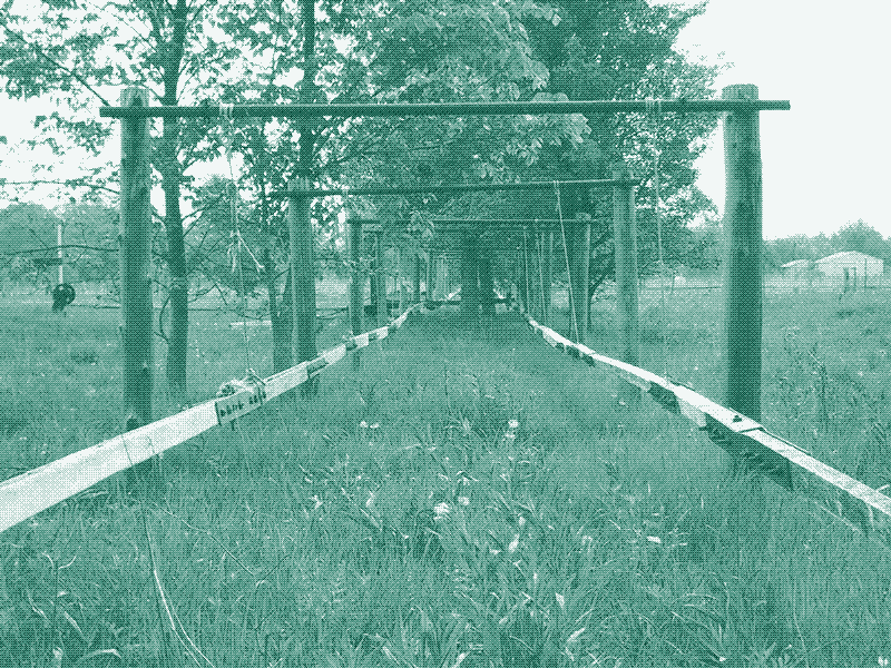
In the Canadian jerker line system, none of the pump jacks were directly connected to the central power. Motion was transferred to the bull wheel and then further subdivided along the main lines using field wheels. As a result, the Pennsylvania jerker line system generally produced web-like patterns, while the Canadian jerker line system usually created linear patterns with dendritic lines.
This can be seen clearly in the James Field in Ontario, which still has both systems still operating. The spider-like systems use metal rods, while the linear systems use wooden rods.
A Balanced system
The web-like layout of the Pennsylvania system offered an important advantage. Because a Stangenkunst was always a combination of horizontal and vertical power transmission, gravity delivered part of the power. A water wheel or steam engine had to deliver all the power needed to make the horizontal stroke that pulled the vertical mechanism upwards, but gravity aided the return stroke. In the case of oil pumping, the weight of the grasshopper pump made the return stroke, saving energy.
This effect was doubled when each well was matched with one in the opposite direction. When the sucker rods in one well raised (the upstroke), those in the opposite well lowered under their own weight (the downstroke), helping raise the rods in the well undergoing the upstroke. In other words, the pumps were powering each other with their own weight. This minimized the load on the engine: the only power required was for overcoming inertia and friction, plus the weight of the oil lifted at each stroke.

The web-like layout of the Pennsylvania system made balancing loads much easier. At all times, half the dead load of rods and mechanisms in the field was being lifted while the other half descended. The steel rods attached to the eccentric could be hooked to, or unhooked from, shackle lines that were connected to the oil pumps. If one well was disconnected, the well in the opposite direction was removed to maintain balance. If this was not possible, the eccentric rod of the disconnected well was hooked to a counterbalance. Since all pumps were directly connected to the central power, one worker could balance the load of all the wells.
This made it possible for a cluster of about 15 to 30 oil wells to be pumped with almost the same engine capacity required to pump one well. In Surface Machinery and Methods for Oil-Well Pumping (1925), H.C. George writes:
“In the early days of the oil industry, all nonflowing wells were pumped individually “on the beam” by steam engines. This system wasted both labor and power, as each well required a man and a steam power plant. At present a group of 15 to 30 similar wells is pumped with a central “power” or “jack” plant with practically the same labor and the same energy capacity as was then used at each well.”
“Many oil wells if pumped individually would show a loss, but operated as members of a group they show a profit. The older fields of Pennsylvania, Ohio, West Virginia, and Illinois exemplify efficiency in group operation. In Pennsylvania the 59,000 operating oil wells show an average of less than a quarter of a barrel production per well per day, yet are being operated at a profit by the group method.”
“Wells of like characteristics, such as pumping time, length of stroke, and size of tubing should be balanced for best results. Some oil companies pump wells of like characteristics at the same time, then take those wells off the power and put on other wells of like characteristics. This practice is common in some of the eastern oil fields, where many wells do not pump more than a few hours per week, and where powers handle 15 to 30 wells, each pumped only several hours at a time.”
Shacklework
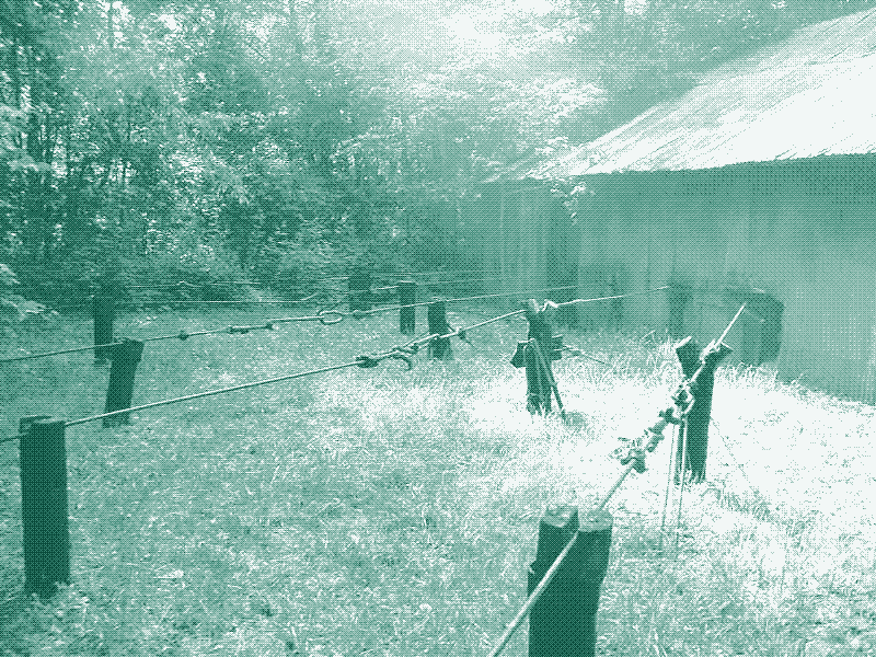
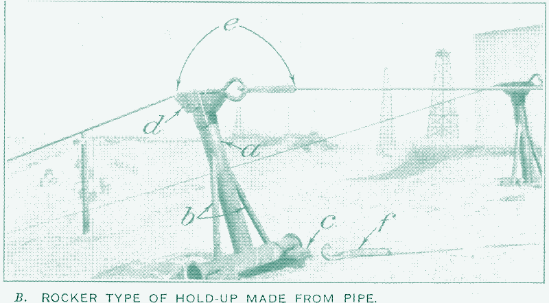
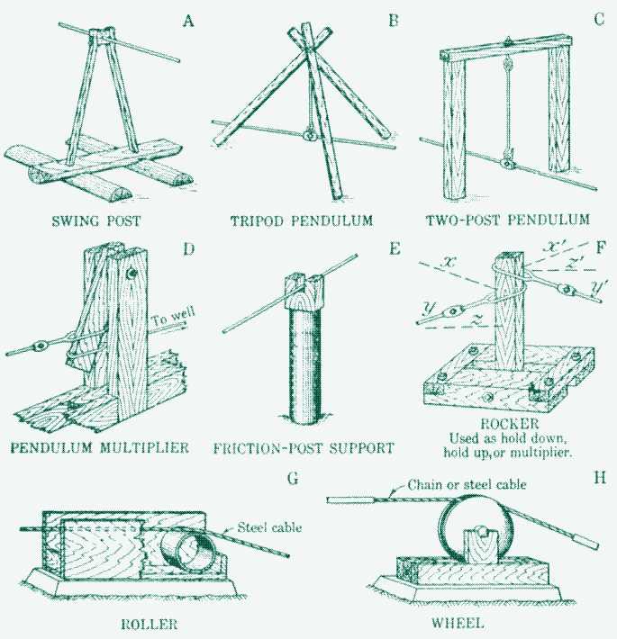
The use of steel cables instead of wooden rods also made it easier to navigate difficult terrain. The Pennsylvania jerker line system made use of a variety of devices to support the lines and change their direction – these were generally called “shacklework”. The steel cables were hung from tripods or supported by “friction posts”, which were fixed in the ground, or “rocking posts”, which were mounted on a pivoting base to allow a rocking motion. “Hold-ups” and “hold-downs” guided the lines up or down, while “butterflies” and “ring swings” allowed them to change direction in order to carry the lines around obstacles.

A “butterfly” was a triangular wooden or metal frame, which allowed up to 90 degree turns and was reminiscent of the V-rods used in the Canadian and pre-industrial system. A “ring swing” was used for lesser changes in direction and was even simpler. It consisted of three rings: one large ring, attached to a another suitable mounting spot, and two smaller rings attached to the large ring and the shackle line. Pendulums and rockers were sometimes used to make the length of the stroke at the well differ from that imparted to the jerker line at the central power.
Often, the shacklework was made from recycled parts, such as discarded rods or pipes. In 1925, H.C. George wrote that “the power or jack plant, and the machinery, shackle line, and jack are all usually standard and purchased from oil-well supply companies, but the shackle line structures are usually designed and built by the operating oil company. This results in a multiplicity of designs and a variety of material.”


In some American towns, shacklework from neighbouring oil fields rocked back and forth over streets and alleys.
Jerker Line Systems Still in Operation
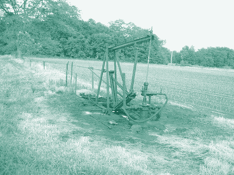
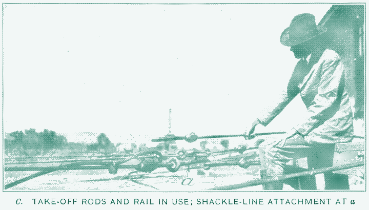
The Pennsylvania jerker line system became the dominant technology used to pump secondary oil wells up till the 1940s, pumping wells up to 3,500 feet deep, and remained in use until the 1960s and 70s. A few installations are stilll running today, or operated until recently. Some of the pictures above and below (there are many more if you follow this link), show the last two oil leases in Flat Rock, Illinois, which used a central power source and rod lines of the Pennsylvania type.
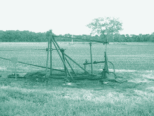
Each is run with a 35 horse power oil-engine and pumps 10 or 11 wells. The rods rest on wood stakes 15 to 20 feet apart and the power moves the rods about 40 cm back and forth. In some places, the rods are rigged to cross a creek or make a turn and head in a different direction. The systems were photographed in 2003, when they were still operational.
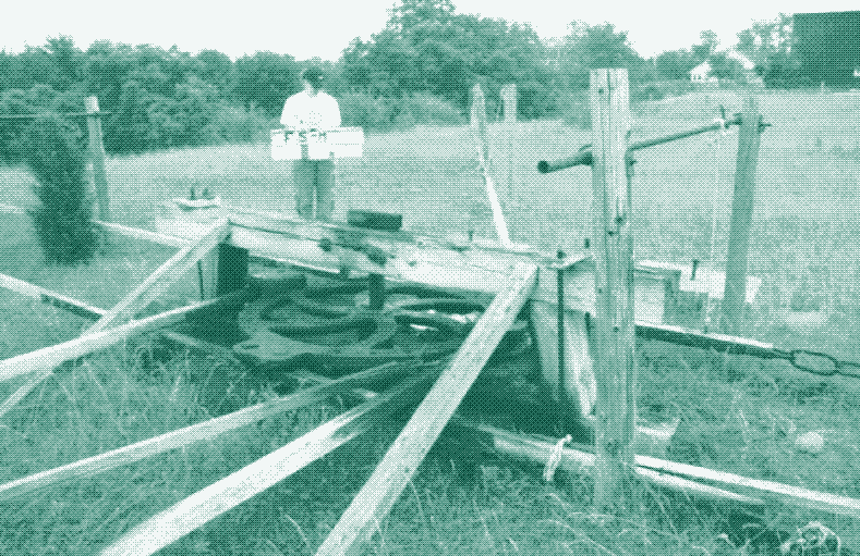
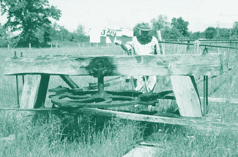
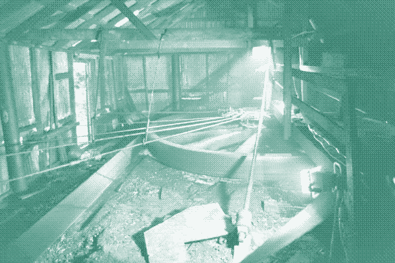
Most remarkable, however, are the central power systems in Oil Springs, Ontario, which have been in operation for 150 years now. Some of these oil fields still make use of the Canadian jerker line system, which was the original technology used to pump oil in the mid-nineteenth century when the fields came into production. Most of the lines on the Fairbank field, and some of the lines on the James field, use wooden rods that operate wooden pump jacks, while some lines on the James field, and all lines on the neighbouring fields, use the original Pennsylvania jerker line system.
While there are obviously sentimental reasons for using nineteenth and early twentieth century technology — the owner of the fields is a great-grandson of John Henry Fairbank, designer of the Canadian jerker line system — the site is not a museum, but a working field that is economically viable. Instead of holding on to the past and trying to recreate a historic oil field, the technology has been continuously improved to maintain its profitability.
More Efficient
One major change in the technology is that steam engines have been replaced by small electric motors, which are cheaper, more efficient and easier to maintain. Most are equipped with reduction gearing, which has made the bulky powerhouse mechanism redundant. Individually-powered pump jacks have replaced the central power system in locations where running a jerker line has failed to be cost-effective, but where the central power system is still in use, it is so because it remains the most efficient and economical.
Even the remaining wooden field rods have been improved: metal hangers that once supported the wooden jerker lines have been replaced with nylon rope for ease of maintenance. The wood for jerker lines and pump jacks is not original, of course, since it is exposed to the elements: the rebuilding of wood equipment has been an on-going historic process.
Oil extraction is usually thought to be large in scale and finite in its lifecycle. However, in Oil Springs, it has been conducted on a continuous, small-scale basis since the late 1850s, while all other oil fields from those times have long been pumped dry using much more powerful technology. One cannot help but wonder how the world would have looked like if all oilmen had stuck with nineteenth century technology.
Future Applications
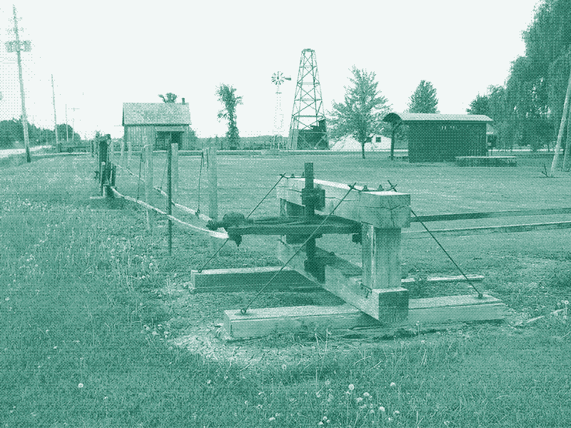
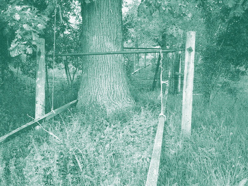
The jerker line system has value, and could be very helpful for those looking for ways to live comfortably life without excessive energy use. The system in the picture below — which still operates today in Oil Springs — is one that any maker could bolt together quickly in no time. With this set-up, one small electric motor could operate four machines in different locations.
Reactions
To make a comment, please send an e-mail to solar (at) lowtechmagazine (dot) com. Your e-mail address is not used for other purposes, and will be deleted after the comment is published. If you don’t want your real name to be published, sign the e-mail with the name you want to appear.
Reactions
The 27th Comrade
Chris, you the best.
I just had to tell you that your magazines—Low-Tech and No-Tech—are really just such a whole lot of collected ingenuity. I can’t say enough “thank you”s.
Darkest Yorkshire
Kris, I should have been clearer. I was not suggesting compressed air just for pumping oil but as a way to store and transmit renewable mechanical energy for industry in general, in the same vein as your windmill and solar factory articles. Looking forward to your thoughts on the subject.
Jan, compressed air cannot be transported over a mile by wood, but it can be by metal pipe, and be far more versatile when it gets there (think of the range of air tools available). Compressed air is a notoriously inefficient energy storage medium, but this is only a problem when it is generated by fossil fuel electricity. If it is generated directly by wind and water then after the initial investment it is largely free energy. In my opinion the combination of energy storage and flexibility of use more than makes up for the inefficiency. Having said that, a jerker line may be the best solution in some situations and a windmill/watermill and stangenkunst combo would be beautiful and hypnotic in an ecovillage, I just don’t expect to see them running through industrial estates.
Jan Steinman
Darkest Yorkshire, can you transmit compressed air over a kilometre via wood?
I’d guess the transmission media for compressed air is probably two orders of magnitude more energetically expensive than that of wood, or even that of steel cables. It would be interesting to see a good emergy analysis comparison of the two.
Kris De Decker
More comments at Metafilter and Hacker News:
http://www.metafilter.com/124540/The-Mechanical-Transmission-of-Power
https://news.ycombinator.com/item?id=5159884
Michael Buck
Kris,
The elementary school I went to had a rider powered merry go round. I have been looking for many years for the mechanism that allowed the reciprocating bars to transmit the rider’s pumping to the center post making the thing spin. I recognize that mechanism in the photo at the top of this post. Can you provide drawings or details about that mechanism? I want to reproduce this merry go round for my friends, well, for myself to spin myself sick like the old days. Any help is so appreciated!
matt
In Switzerland cables and belts have been used to power textile factories. The energy flow is constant with a continuously moving endless cable. Different machines could have different speeds by simple gearing.
One huge problem with moving power transmission is safety. There where many accidents because an arm was bought in the diving mechanism. With todays safety levels the transmission would net to be completely enclosed. Also with electricity an emergency stop is ready to implement.
Peter Allen Sharp
Excellent article. I’m developing an unbalanced, single-blade, vertical axis windmill (called the Bird Windmill) that will reciprocate cords to transmit energy via a jerker line. Many such small-scale windmills will be able to concentrate power at a single location to drive a wide variety of devices, including a generator or air compressor (perhaps using the LightSail system for conserving the energy of compression). My goal is to provide off-the-grid farms and villages with reliable, low-cost power. The system may prove to be cheap enough to compete with conventional, large-scale wind turbines, but it’s too soon to tell. I’m still at the model stage. Here is a video showing me testing a very cheap blade:
https://www.youtube.com/watch?v=WO4ZaTEl1Ok
John Hewat
I saw this and said ‘I don’t believe it!’
Human ingenuity. Brilliant!
G.
Agreed: this is brilliant. Though, it occurs to me that ordinarily, reciprocating motion applied to mass has an inertial loss at each end of each stroke. What means if any, were used to compensate for that? Or is the system sufficiently economical to operate, that the inertial losses don’t matter?
If the field lines were suspended from pendulums hung from pivots above the lines, that would partially compensate: As a stroke reached the end of the arc of the pendulums, inertia would be working against gravity, thereby effectively absorbing energy and storing it as the lines were raised by the pendulums at the ends of their swing. As the stroke in the opposite direction began, gravity pulls the lines down and partially compensates for the inertia of getting them started back in the opposite direction.
This is a bit of a wild long shot, but: What about optimizing for, and taking advantage of, the resonant frequency of a system? If a mechanical transmission system is built with elements of the correct size and mass, operated at the correct frequency of reciprocation, it should theoretically develop a resonance that improves the efficiency of the output. Each installation would need to be carefully calculated for this, but the variables are pretty well known and understood.
Jim of Olym
I remember such a system in Los Angeles, in the Bunker Hill area where there were old oil wells which worked from a central cable system. Used to see them from the streetcar from Glendale. (back around 1950) Remember streetcars? they were electric, until GM forced them to get busses.
Bob
I am in the process of building an off grid home with a 150 foot well. A 12 volt well pump is about 1500 dollars for a good one. After living on a sailboat for most of my life, I learned not to depend on anything electrical, so that leaves mechanical. I saw one mechanical pump on the internet for around 600 dollars plus the pipe. Still probably about $800 to $1000. The other one is about $7,000, ain’t gonna happen.
I went to the oil industry for a pump design because that is the most extreme pumping conditions. The most obvious way to power it has already been figured out by GUESS WHO ? The oil industry. While studying pump jacks I found this page. Low and behold I will have a gas generator a hundred feet away.
Gear it down to 6 rpm
jerk line
pump jack
pump
That’s it, maybe $300. Manual, freeze proof, can be operated with gas engine running on waste motor oil, gas, diesel, propane, wood gas etc etc etc.
The biggest problem with gas engines is the carburetor. All those sources of fuel do not require a carburetor. Now I have a much more reliable source of power.
Thank you oil industry
Travis
Thanks for the read. The land I bought a while back had one of these wells and I wasn’t sure what it was! We still get oil and house gas off the wells.
Phil Ross
Just a few comments, based on my work documenting these systems for the Institute for History of Technology and Industrial Archaeology (WVU) and the Historic American Engineering Record in the 1990s. That was the decade that the final survivors approached the economic limits of their useful lifespans. Their technological persistence is a testament to their simplicity and efficiency, and the willingness of some operators to maintain historic equipment for history’s sake.
My research suggests that the “jerker line” terminology is culturally restricted to the Canadian pantograph or “push/pull” systems. In the Appalachian region they are referred to as rod lines, central powers, or a combination of the two (Pennsylvania), or shackle lines (West Virginia and Ohio). In Pennsylvania the rod lines are typically either reused sucker rods or purpose-built pull rods with clamshell connectors, and in West Virginia and Ohio the shackle lines are mostly wire rope. The structure that shelters the machinery is a “power,” “powerhouse,” or “central power.” I did not document any survivals of the midwestern or western systems so I am unfamiliar with any different terminology there. The historic literature on petroleum engineering refers to them as jack plants and central power systems.
A well documented and detailed description dating to 1863 shows that push/pull powers likely originated in the West Virginia shallow sand fields, and subsequent US patents followed closely. Most Pennsylvania operators of this era found it more profitable to chase new flush production rather than pump old production, with the exception of a lubricating oil pool at Franklin in Venango County, and that’s where the earliest multiple-well pumping systems originated in that region. The claim that J.H. Fairbank introduced the Oil Springs system in 1863 is based on folklore–family tradition– rather than documentary evidence. But it’s possible; technology was very migratory among oilfields in this early era, even with the distances between them. The fraternity of oil men was a very small one, and that of its practical engineers even smaller. That the Canadian jerker system still exists is largely due to the fact that the Petrolia/Oil Springs wells are closely spaced and extremely shallow, with relatively little downhole weight to lift and inertia to overcome. Push/pull systems, especially with loosely-suspended strap-coupled wooden pitmans connecting the field wheels, are not suited to the kind of weight and inertia typical of 1500- to 2000-foot-deep Appalachian wells, where the rod lines operate under carefully balanced tension. Push/pull systems were quickly superseded in the Appalachian fields by rod line systems as they became available.
There was one notable outlier in the West Virginia shallow lubricating oil fields that was pumped with an endless wire cable system. It was adapted for pumping a large number of wells, but mostly sequentially rather than simultaneously since the loads were difficult to balance. This system managed to operate largely unchanged for an entire century–from the 1870s to the 1970s–as a remarkable example of technological persistence in uniquely favorable conditions.
I documented lots of interesting and ingenious devices for changing direction, managing friction, and counterbalancing rod loads, some at a fair distance from the power. Some systems pumped single wells over a mile distant from their powers. One pumper operated his washing machine with a shackle line. Another pumped a single well with a water power, consisting of a crank and disc mounted on an undershot waterwheel that was located on a creek dammed just for this purpose. When the pond was emptied, the well was done pumping. Many were adapted for steep hillsides by installing bandwheel eccentrics parallel to the slope of the hill. Very few of these systems were built on level ground, especially in the Appalachian field, and the typically rugged topography presented major challenges for using both standard shacklework components and repurposed material at hand. Every solution was completely unique, and I remain amazed at the ingenuity and engineering acumen that went into solving these problems.