During the second half of the nineteenth century, water motors were widely used in Europe and America. These small water turbines were connected to the tap and could power any machine that is now driven by electricity. As we have seen in a previous article, operating motors with tap water was not very sustainable. Because of the low and irregular water pressure of the town mains, these motors used unacceptably high amounts of drinking water.
While the use of water motors in the US came to an end early in the twentieth century, the Europeans found a solution for the high water use of water motors and took hydraulic power transmission one step further. They set up special “power water” networks, which distributed water under pressure for motive power purposes only, and switched to a much higher and more regular water pressure, made possible by the invention of the hydraulic accumulator.
Almost all these power water networks remained in service until the 1960s and 1970s. Hydraulic power transmission is very efficient compared to electricity when it is used to operate powerful but infrequently used machines, which can be distributed over a geographical area the size of a city.
“The use of water is a curiously neglected subject in the literature of engineering. As a romantic or popular facet of engineering, hydraulic power has never caught the public eye like the steam engine, the locomotive or even the internal combustion engine.” Ian McNeil, Hydraulic Power, 1972
The theoretical basis for hydraulic power transmission was laid in 1647 by French whizz-kid Blaise Pascal. By means of experiments, he discovered that water — unlike air — is virtually incompressible and transmits pressure equally in all directions.
The implications of the “hydrostatic paradox” were demonstrated in Pascal’s “machine for multiplying forces”, illustrated below. It consists of two upright cylinders, connected together by a pipe. The whole system is filled with water and sealed water-tight. One cylinder contains a small diameter plunger, while the other cylinder contains a plunger that has a cross-sectional area 100 times larger.
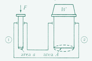
Pascal demonstrated that if a weight is placed on top of the small piston, it will be able to raise a weight placed on top of the larger piston that is 100 times heavier. Pascal’s machine thus allowed forces to be multiplied — in the example above, the ratio of force output to force input is 100 to 1. In other words, you can produce an output force of 100 kg for an input force of only 1 kg.
A Machine for Multiplying Forces
Force multiplication was anything but new in the 1600s. More simple devices such as pulleys, gear trains, capstans, winches and treadwheels — all variations on the 7,000 year old lever — could also derive a high output force output from a small input force. For example, the Romans built cranes with a mechanical advantage of up to 70 to one, meaning that one man exerting a force of only 25 kg could raise a weight of 1.75 tonnes.
However, the hydraulic version of the lever has one outstanding advantage over earlier mechanisms: the friction loss is very small and independent of the mechanical advantage. Therefore, the possible multiplication ratio is almost infintely greater and both pistons may be a considerable distance apart — up to about 25 km, as we shall see.
In hydraulics, friction loss is independent of the mechanical advantage, therefore the possibile force multiplication ratio is almost infinite
Increasing force multiplication could be done by either extending the proportion between the diameter of both plungers, or by applying greater power to the smaller piston. In common with the earlier mechanisms, what is gained in mechanical advantage is lost in velocity ratio.
If a small hydraulic force is converted into a larger force, its speed of operation will be reduced in exactly the inverse proportion, because the distance traversed increases in the same proportion as the force. For example, a person pressing down the small piston 10 centimetres would move the other piston up only 1/100th of that distance.
Consequently, in a closed system, the heavier weight could be lifted only over a very limited distance, depending on the length of the plunger. However, this limit is removed when more water is added to the system and the smaller piston, instead of coming down just once, makes a number of strokes — in other words, when it functions as a pump. In this case, the larger piston will keep rising.
The Hydraulic Press
Pascal could only prove his point indirectly, as the available materials at the time were not strong enough to withstand the pressure. It would take another century and a half before hydraulic force multiplication was put into practice. Its first use was not a lifting device, but rather the opposite: the hydraulic press, which generates a compressive force.
The conventional screw press of the time, little developed since the Romans had used it for pressing olives and grapes, required a great effort to operate, had large frictional energy loss (+80%), and could not have exerted more than 25 tonnes load. (The screw, which converts rotational motion into linear motion, is basically an inclined plane wrapped around a cylinder).
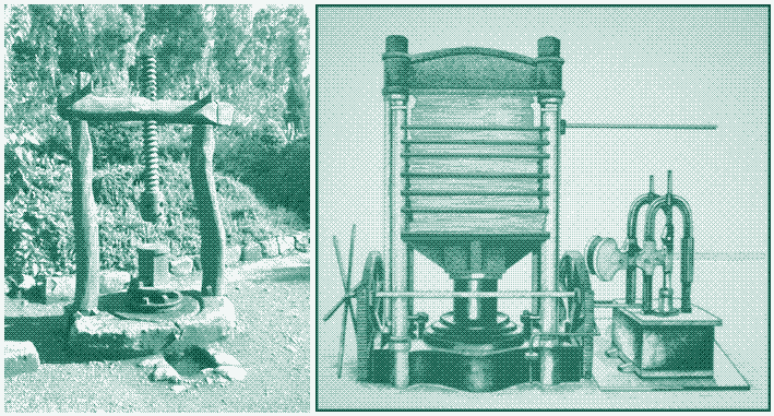
The hydraulic press was invented in 1796 by English locksmith and carpenter Joseph Bramah. It was entirely based on the theoretical work of Pascal. Bramah’s hydraulic press, which was driven by a hand-operated pump, brought a large increase in the load that could be exerted by a human.
With the available materials at the time, Bramah achieved an overall ratio of 1,000 to 1, which means that an effective load of 60 tonnes on the lifting piston could be balanced by a mere 60 kg on the pump handle. The efficiency of the hydraulic press was over 90%.
Harbours and Dockyards
In spite of its eminent suitability for crane operation, hydraulics made little progress in this field during the first half of the nineteenth century. This was largely due to the problem of reliably and efficiently translating the linear motion of a ram to rotary motion of the crane barrel or drum. During the first half of the nineteenth century, cargo handling in harbours, dockyards and railway yards was still done by means of human powered cranes, but the need for taller and stronger cranes was great.
Starting in the 1830s, iron began to be used as a material for ship building, with a parallel growth in the dimensions of ships. Conventional lifting systems were no longer adequate. In most countries, the solution was found in the steam powered crane, which appeared in the 1850s. However, in harbours and dockyards in Britain, a worthy alternative appeared: the water powered crane.
During the first half of the nineteenth century, cargo handling in harbours, dockyards and railway yards was still done by means of human powered cranes
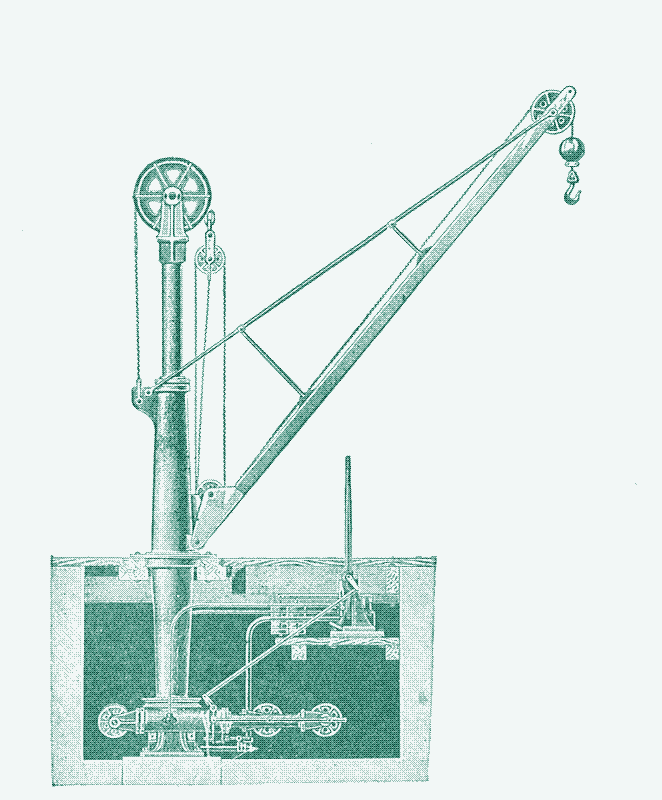
British engineer William Armstrong started designing and operating powerful hydraulic cranes in the 1840s. Being fully aware that hydraulics was best adapted for giving a slow, steady motion, Armstrong deviced a method of lifting the load at one stroke of a ram or piston, multiplying the motion sufficiently by means of pulleys.
However, his efforts were complicated by the low and irregular pressure of the town mains, which was the power source for these machines. The maximum power output of a water powered machine is determined by water pressure and water flow. In the town mains, water pressure was (and often still is) supplied by a water tower. Because the practical height of a water tower is limited, so is the water pressure. A 50 m (165 ft.) tall water tower can produce a water pressure of 70 pound-per-square-inch (psi).
Consequently, the only way to further increase the power output of a crane running on water from the town mains is to increase the water flow. However, this raises potable water consumption and increases the size and costs of pipes, valves, cylinders, and other parts of the system. Moreover, if there is a higher than average demand for potable water from other users, the water level in a water tower will fall, and so will the water pressure and the power output of the machine.
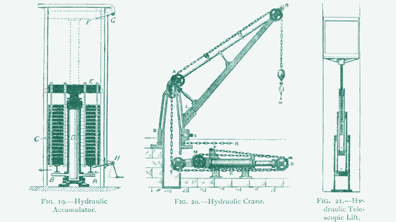
The Hydraulic Accumulator
In 1851, Armstrong came up with an alternative solution that solved these issues: the hydraulic accumulator. Although much more compact than a water tower, it could produce a regular water pressure of 700 psi or higher — at least 10 times the water pressure in the town mains. This allowed to produce an order of magnitude more power without raising water consumption or increasing the size of system components.
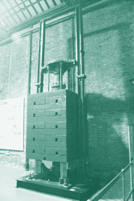
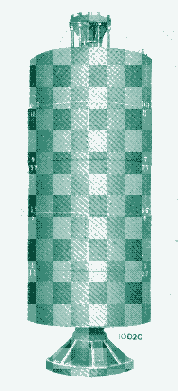
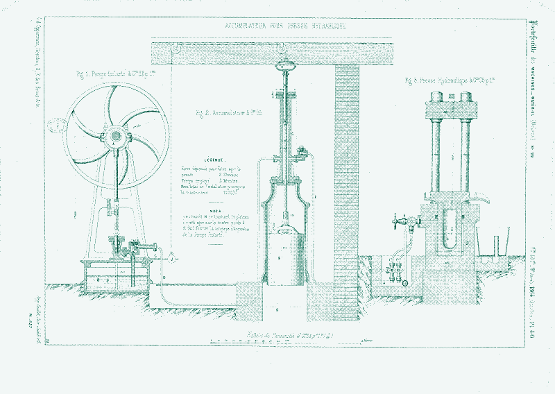
Armstrong’s hydraulic accumulator was a contraption in which a ram or piston exerted pressure on the water in a vertical cylinder. The piston was loaded by dead weight ballast, which generally took on the form of a cylindrical ballast container surrounding the central cylinder (image below, on the left). The container was filled with crushed rock, scrap iron or other ballast material.
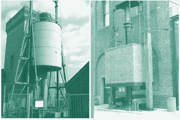
For a water pressure of 700 psi the ballast was about 100 tonnes, acting on a ram of about 45 cm in diameter with a vertical stroke of 6 to 7 meters. Another type of accumulator utilised a rectangular platen to support a brickwork ballast (image above, on the right) or steel slabs. Hydraulic accumulators could be set up outdoors, or housed in a purpose designed building.
In comparison with a water tower, a hydraulic accumulator could deliver ten times more power, and maintain an even pressure all over the network
The workings of the hydraulic accumulator are somewhat similar to those of a water tower. The central cylinder has a water inlet and outlet at the bottom. Water from the docks could be pumped in through the inlet by a steam powered pump, raising the piston, while it could be pushed out through the outlet into the mains for distribution, lowering the piston.
Energy was stored by upward movement of the ram and recovered upon its descent. The pumping rate of the steam engine was regulated in function of the water level in the accumulator, either automatically via mechanical linkages or via the aid of a human being.
Contrary to a water tower, however, the accumulator could maintain an even pressure all over the system regardless of the volume of water in the cylinder, because it’s the weight of the ballast and not the weight of the water that creates the pressure — in other words, the hydraulic accumulator gives pressure by load instead of by elevation.
With a charging/discharging efficiency above 98%, and no self-discharge, the hydraulic accumulator was an extremely energy efficient device.
Water Powered Factory Machinery
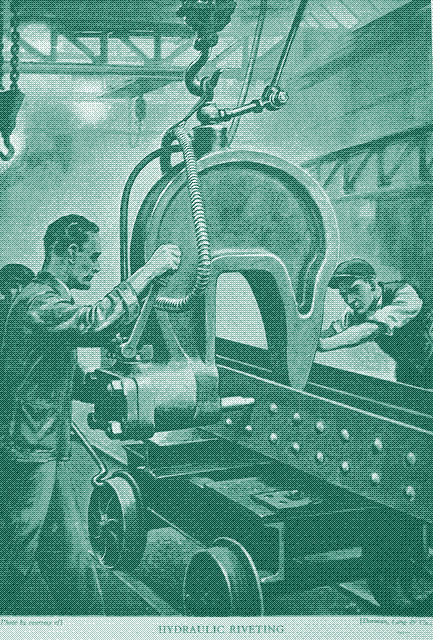
The introduction of the hydraulic accumulator had two important effects. First, it greatly expanded the range of hydraulically operated machines. The water motors connected to the town mains were household devices and workshop tools. But Armstrong and other engineers adapted high pressure water to a variety of industrial applications that required great power such as forging, punching, stamping, flanging, shearing and riveting (the predecessor of welding).
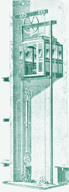
In harbours, high pressure water not only operated cranes and hoisting machines handling cargo on docks and in warehouses, but also lock gates, swing bridges, boat lifts, and graving docks. At railway yards, hydraulic power transmission was used for freight handling and for moving railway cars (using hydraulic capstans), as well as for operating turntables, elevators and traversing mechanisms. All these applications of hydraulic power would have been impossible with the low and irregular pressure prevailing on the town mains.
To give an idea of the importance of hydraulic power, it suffices to look once more at the evolution of lifting devices. In 1586, a 344 ton obelisk was moved between squares in Rome. Domenic Fontana, master builder of the Vatican, raised the obelisk with the help of 40 capstans worked by 400 men and 75 horses. In 1878, John Dixon raised another obelisk — Cleopatra’s needle, weighing 209 tons — using four hydraulic lifting jacks, worked by four men.
Power Water Networks
Secondly, the hydraulic accumulator made it possible to transmit power efficiently over large distances. For a 30 cm diameter pipeline, the pressure drop in water distribution amounts to about 10 psi per mile, a figure that is independent of water pressure. Thus, if you transmit water with a pressure of 70 psi over a distance of 7 miles (12 km), all energy is lost. But if you transmit water over the same distance with a pressure of 700 psi, a water pressure of 630 psi remains, which comes down to a transmission efficiency of 90%.
The high transmission efficiency of high-pressure water led to the construction of at least a dozen public power water networks with accumulator storage, half of them in Britain, in which centrally located steam engines pumped water into hydraulic accumulators that distributed high pressure water over a large geographical area. One or more accumulators would be installed at each hydraulic power station and others could be sited at strategic points along the supply main as sub-stations.
The idea of a truly hydraulic power network — analogous to the electric grid that came a bit later — was already outlined in a 1812 patent by Joseph Bramah, the inventor of the hydraulic press.
From the 1870s to the 1890s, hydraulic power networks were established in the leading industrial cities of Britain: Kingston upon Hull, London, Liverpool, Birmingham, Grimsby, Manchester and Glasgow. Dock and railway companies pioneered the technology, and remained the most important users for decades.
However, power water was also running manufacturing processes in factories, operating elevators in public, private and commercial buildings, and activating household devices and workshop tools. Anybody who was lucky enough to have a mains running through the street could connect to the public network. Power water consumption was metered, as it happens today with potable water and electricity.
The idea of a truly hydraulic power network — analogous to the electric grid that came a bit later — was already outlined in a 1812 patent by Joseph Bramah, the inventor of the hydraulic press. But Bramah, who also conceived the hydraulic accumulator and the hydraulic crane, was ahead of his time. It took another sixty years before his ideas were brought into practice by Armstrong and his contemporaries.
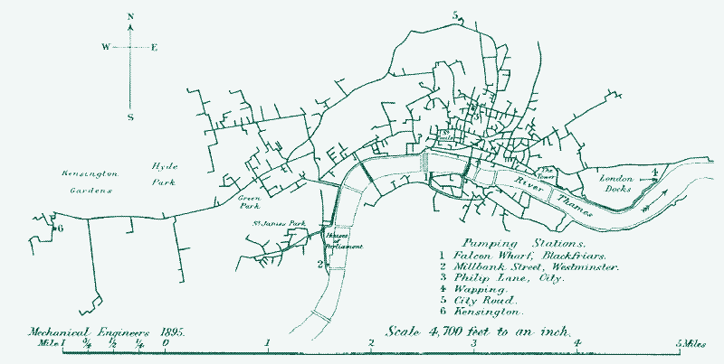
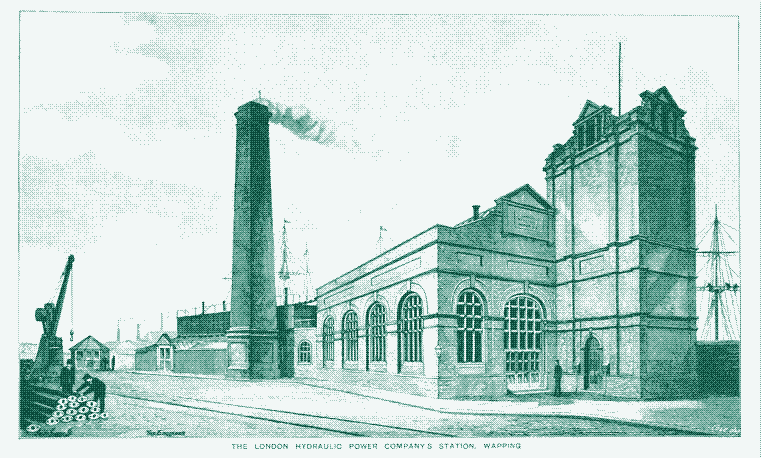
London Hydraulic Power Company
The most extensive hydraulic power network was built in London, operated by the “London Hydraulic Company”. At the company’s peak in 1917, five interconnected central power stations pumped high pressure water in about a dozen hydraulic accumulators and almost 300 km of supply mains, powering more than 8,000 machines and serving most of the city. In London theatres and other cultural buildings, power water was moving floors, organ consoles, fire curtains and stages. Water under pressure worked water pumps and lifted the bascules of the Tower Bridge.
Fire hydrants were also advantageously served by the high pressure system and several hundreds of them were connected to the London Hydraulic Power Company’s mains. These fire-fighting systems increased the pressure of the domestic water mains by injecting a small amount of high pressure water in them, using a jet pump. By itself, water at high pressure from the hydraulic power mains could not be supplied in adequate quantity to have an effect on a large fire, while the domestic supply mains had enough quantity but not enough pressure to reach the top floors of buildings.
In London, five interconnected central power stations pumped high pressure water in a dozen hydraulic accumulators and almost 300 km of supply mains, powering more than 8,000 machines and serving most of the city.
Another remarkable application of high pressure water in London was the Silent Dustman, a water powered vacuum cleaning system that came on the market in 1910. Several large hotels were completely “wired” for this system: water from the town mains was used in a jet pump to produce a vacuum in a pipe to which the system was to be fitted. Along these pipes were a number of nozzles to which flexible hoses could be fixed. Thus the dirt from the sweepers was drawn into the hydraulic pipe and carried away into the drains. The system, which operated silently and efficiently, remained in operation until 1937.
In London, however, hydraulic power does not seem to have made a great impact on the domestic scene. In The Hydraulic Age (1980), B. Pugh notes that this was “possibly due to the fact that in its day domestic labour was cheap and in plentiful supply. Had present-day conditions operated then possibly the story would have been different since the potentialities of hydraulic power were not less than those of electricity today.”
Most public power water networks supplied water under a pressure of 700 to 800 psi (48 to 55 bar), with the exception of Manchester and Glasgow, where water was pressurized to 1120 psi. In these cities, there was a heavy demand for power for hydraulic presses used for baling, an application that required a higher pressure.
Power Networks Outside Britain
The British power systems inspired similar networks elsewhere: Antwerp in Belgium, Buenos Aires in Argentina, and Melbourne and Sydney in Australia. While the Australian systems were reminiscent of those in Britain (with 80 km of mains, the one in Melbourne was the second largest ever built), the Argentinian system was used to pump sewage, and the network in Antwerp was aimed at the combined production of mechanical power and electricity. The latter was an attempt to overcome the very high transmission losses of electricity at the time.
In The Hydraulic Age, B. Pugh writes that:
“For power transmission, the early electric stations were faced with the same difficulties as the hydraulic power stations, their voltage being analogous to working pressure, and voltage drop due to mains resistance analogous to pressure drop due to pipe friction. The early electric public power stations were direct or continuous current stations, the voltage of generation essentially being only slightly higher (by the voltage drop in the cables) than at the consumer’s premises which for safety reasons had to be less than 250 volts. Due to voltage limitation, the area of supply as well as the amount of power that could be transmitted was limited.”
The network in Antwerp was aimed at the combined production of mechanical power and electricity.
Since 1865, Antwerp had been using a high pressure hydraulic network for powering cranes, bridges and sluices in the harbour. To this was added a second network in 1893, which distributed high pressure water to electric substations scattered across the city (twelve according to the plan, but only three were built). There, water turbines generated electricity which was distributed in a radius of 500 m via underground electric conduits — this was about the distance at which low voltage could be distributed efficiently.

The Antwerp system, which was used for operating street lighting, thus did on a large scale what water motors connected to dynamos did on a small scale with water from the town mains (see the previous article. About 66% of the hydraulic energy was converted to electricity. At its peak, the network reached a length of 23 km with an output of 1200 hp. There were also a number of places in London where consumers ran small electric generators from the hydraulic supply.
Power Water Versus Electricity
The breakthrough in high voltage electric transmission at the turn of the century made systems like those in Antwerp immediately obsolete. The electricity generating part of the network disappeared in 1900. Producing water under pressure in order to produce electricity involves a fourfold energy conversion, which is needlessly wasteful if you can just produce electricity and transport it efficiently.
The expansion of efficient electrical transmission also stopped the construction of other large-scale power water networks before the century was over. “Had these systems been started some years earlier, they might have become vastly more popular”, writes Ian McNeil in Hydraulic Power (1972). “A few years later, and they would probably never have been built at all.”
However, almost all public power water systems that were built between the 1870s and 1890s remained in service until the 1960s and 1970s, eventually using electric motors instead of steam engines for pumping. The power water network operated by the London Hydraulic Company, the last to survive, worked until 1977. Most of the public power water networks kept growing during the first decades of the twentieth century, reaching their heydays at the end of the 1920s. The fatal decline came only when factories started leaving the cities in the 1960s and 1970s.
If electricity is the most efficient and practical way of transmitting and distributing power, then why did almost all power water networks remain in service for almost a century?
This raises two questions. First, why didn’t power water become the universal method of power distribution that Joseph Bramah and William Armstrong had envisioned? And second, if electricity is the most efficient and practical way of transmitting and distributing power, then why did almost all power water networks remain in service for almost a century?
Advantages of Electric Power
As a power transmission technology, power water has three important disadvantages in comparison to electricity. First of all, electricity can be transported efficiently over much longer distances. Hydraulic power transmission was (and still is) at least as efficient as electric power transmission up to distances of 15 to 25 km. Beyond those distances, however, electric transmission is a clear winner.
A second shortcoming of hydraulic transmission is that a complex distribution network introduces additional energy loss. Every curve or bend in the mains increases friction losses. The more intricate the network, the less efficient it becomes. Electric transmission doesn’t have this problem, at least not in a significant way. The friction losses in the water mains limit the amount of machines that can be attached to a power water network, while electricity can be subdivided almost infinitely.
The third limitation of power water is the limited capacity of a hydraulic transmission line. Water under pressure can only be moved through thin pipes at walking speeds in order to avoid excessive friction losses. At higher speeds, the loss of friction increases as the square of the velocity and efficiency goes down fast, even over relatively short distances. This limits the flow rate and thus the power that could be delivered by a hydraulic transmission line.
Using a 10 to 12 cm diameter pipe — a common size in most high pressure system at the time — a hydraulic transmission line could produce a maximum continuous power of 115 to 205 horse power (85 to 150 kW). High voltage electric transmission lines of similar size can carry an amount of power that was orders of magnitude greater than that.
Advantages of Power Water
However, none of these disadvantages mattered for the power water networks that we have discussed. These were all decentralized systems, with machines no more than 15-25 km away from the power source. Secondly, because the hydraulically operated machinery in harbours, railway yards, factories and buildings was characterized by slow motion and infrequent use, the slow transmission speed of power water presented no obstacle.
With the exception of the short-lived electricity generating system in Antwerp, none of the Armstrong-type power water networks supplied power to a large amount of continuously operating machines. (But note the medium pressure power water networks in Switzerland. Lastly, because a power water network operated relatively few (but very powerful) machines, friction loss through bends and curves in the network was limited.
The limitations of hydraulic transmission were very well understood at the end of the nineteenth century. However, engineers also grasped the unique benefits of the technology, which still hold today. For example, Robert Zahner, an advocate of yet another alternative to electricity, compressed air, wrote in The Transmission of Power by Compressed Air (1890) that:
“The practical incompressibility of water renders the hydraulic method unfit for transmitting regularly a constant amount of power. It can be used to advantage only where motive power is to be accumulated and applied at intervals, such as raising weights, operating punches, compressive forging and other work of intermittent character, requiring a great force through a small distance.”
Hydraulic transmission is “admirably adapted for use with heavy machinery and equipment in operations requiring marked concentration of power, reciprocating straight-line motion, and intermittent action”, wrote Louis Hunter in The Transmission of Power (1991). The main excellence of the hydraulic accumulator is that it allows to operate machines that require much more power than the energy source can supply — Pascal’s “force multiplication”.
The limitations of hydraulic transmission were very well understood at the end of the nineteenth century. However, engineers also grasped the unique benefits of the technology, which still hold today.
When high force or torque are needed, hydraulic power systems are a much more compact and energy efficient solution than mechanical or electric drives. Both electric motors and combustion engines often need mechanical power transmission (gears, chains, belts) to convert their high rotational speed to a slower speed with higher torque.
Likewise, hydraulic power systems easily produce linear motion using hydraulic cylinders, while electric power requires costly linear motors or mechanical power transmissions such as rack-and-pinion assemblies. Hydraulic and electric power are complementary in this sense: one of the limitations of power water transmission was the relative difficulty of converting linear motion to rotary motion.
Pelton wheels were the most obvious choice, but their high rotational speed involved the use of gearing for the operation of slow speed machinery. A number of hydraulic engines of the ram type was available to supply rotative power involving variable or slow speed operation, but these engines had few advantages compared to electric or mechanical drives.
A third important advantage of hydraulics is that the power is always readily available in the pipes and in the accumulator, but when there is no demand there is no waste. When none of the machines in a power water network was in operation, the hydraulic accumulators kept the lines pressurized without using any energy. This advantage is especially relevant when machines are used intermittently.
Hydraulics Today
Hydraulic power is still in use today, especially in heavy industrial equipment that requires a slow but powerful linear motion, and in mobile construction machinery such as excavators. However, the raised-weight hydraulic accumulator and the power water networks have disappeared.
The pressurized fluid is no longer water but oil, mixed with additives. (Vegetable oil had been used as a hydraulic medium in the 19th century). Unlike water, oil doesn’t freeze and is not corrosive. However, it makes hydraulic power more expensive and it obviously doesn’t permit the exhaust fluid to end up in the sewer network, the docks or the sea.
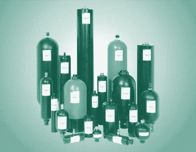
Partly as a consequence of the use of oil, there evolved the self-contained hydraulic power pack consisting of pump, hydraulic accumulator, and return flow systems, ready to be coupled to an electric motor or a diesel engine. The hydraulic accumulators in these systems are much smaller, they use a gas to compress the fluid, and they do not maintain a steady pressure.
While the practical benefits of hydraulics remain — a large amount of power can be transferred and controlled precisely using very compact components — the modern approach erases an important efficiency advantage specific to the more centralized power water networks of the nineteenth and twentieth century. In a city-wide power water network, a comparably small central power source — a handful of hydraulic accumulators — could operate a large number of very powerful machines. The pumping engines didn’t have to be dimensioned for peak loads.
A great advantage of power water networks was that comparatively little power capacity was required to operate a large number of powerful machines over a wide area.
B. Pugh laments this evolution in The Hydraulic Age (1980):
“One century ago, only a few very large machines — swing bridges and an occasional hydraulic press — had their own individual pumping equipment. More recently, this trend spread throughout hydraulically operated machinery of all types and sizes, and is accepted practice today. With unit hydraulic power packs each piece of equipment will be driven by its own motor and will have its own instrumentation, filters, etcetera, which will call for periodic inspection and maintenance.”
“The motor will run continuously while the unit is in use regardless of the load on the pump it drives. In the case of a number of such units not all will be working to capacity all the time. Appreciable economy could be effected by having a central pumping plant to supply a number of units and due to the diversification of the load the maximum load at any one time will be less than the sum of the individual maximum loads.”
“An advantage of a large station over a number of smaller ones lies in the ability to meet diversity of demand. A number of small, independent power stations must each have sufficient capacity to meet the peak demand of its own area of supply and the peaks will not occur at the same time. A large station, embracing the total area of a number of small stations, will need only to meet the maximum simultaneous demand and this will normally be less than the sum total of the local peaks.”
Alternatives to Electricity
Just like mechanical power transmission technologies — such as jerker line systems and endless rope drives — power water networks have disappeared largely because electric transmission has superior efficiency over long distances. However, in a more decentralized energy system based on renewable energy, all these forgotten alternatives for electricity deserve to be reconsidered for specific purposes. Raised-weight hydraulic accumulators could be solar, wind or even pedal powered.
Around 1900, the superiority of electricity for transmitting power over very long distances was not disputed. For moderate distances, however, quite a few authors doubted its usefulness. For example, R. Kennedy wrote in Modern Engines and Power Generators (1905):
“Electricity offers paramount advantages for power transmission to a distance in most cases. Electrical engineers, however, claim far too much for it. They are apt to forget other means for transmitting power, which means have paramount advantages over electricity in a good many cases.”
W.C. Unwin, the author of the most complete nineteenth-century book on power transmission (On the Development and Transmission of Power from Central Stations), expressed a similar concern in 1894:
“Granting that electrical distribution will play an important part before long in the development of systems of power distribution, there is a popular tendency at the moment to regard too exclusively electrical methods, and to overlook other means of power distribution which have been usefully applied in the past, and will, in suitable conditions, be still employed in the future… For transmission to moderate distances there is a choice of several means of transmission, and electrical distribution has not in such cases and up to the present established any universal superiority.”
In the next installment of our power transmission series, we will discuss compressed air, which is probably the most usable alternative for electricity.
This article is dedicated to Charles Steele. RIP.
Sources (in order of importance):
The Hydraulic Age, B. Pugh, 1980
Hydraulic Power (Industrial Archaeology), Ian McNeil, 1972
On the Development and Transmission of Power from Central Stations, W.C. Unwin, 1894. Also here.
Hydraulic Machinery, with an introduction to hydraulics, R.G. Blaine, 1897
A History of Industrial Power in the U.S., 1780-1930: Vol 3: The Transmission of Power, Louis C. Hunter and Lynwood Bryant (1991)
Modern Engines and Power Generators; a Practical Work on Prime Movers and the Transmission of Power, Steam, Electric, Water and Hot Air — Volume One, R. Kennedy, 1905
Modern Engines and Power Generators; a Practical Work on Prime Movers and the Transmission of Power, Steam, Electric, Water and Hot Air — Volume Six, R. Kennedy, 1905
Power and Power Transmission, E.W. Kerr, 1908
Remnants of Early Hydraulic Power Systems (PDF), J.W. Gibson, 3rd Australasian Engineering Heritage Conference 2009
L’eau à Genève et dans la région Rhône-Alpes: XIXe-XXe siècles, Serge Paquier, 2007
L’eau des villes: Aux sources des empires municipaux, Géraldine Pflieger, 2009
Revue technique de l’Exposition universelle de 1889, Section II, récepteurs hydrauliques (PDF), 1893
L’usine des forces motrices de la Coulouvrenière à 100 ans: 1886-1986, Services industriels, 1986
Waterdruk in Antwerpen. Een stroom van elektriciteit", Dirk De Vleesschauwer and Noël Kerckhaert, 1993
Kroniek van de stroomverdeling van Antwerpen-stad tot de Rupelstreek tot de Eerste Wereldoorlog, Geschiedkundige Studiegroep Ten Boome. (website)
Het Zuiderpershuis, een monument. Brochure bij de tentoonstelling n.a.v. Open Monumentendag 2010 (PDF), Steunpunt Industrieel en Wetenschappelijk Erfgoed, 2010.
The Centrifugal Pump, Turbines, and Water Motors, Including the Theory and Practice of Hydraulics, Charles Herbert Innes, 1898
Metropolitan Works: Collected Papers on London History, Ralph Turvey, date unknown.
Hydraulic Power Company, The Vauxhall Society, 2012 (website)
London Hydraulic Power Co, Grace’s Guide, date unknown (website)
Hydraulic Power, NSW HSC Online (website)
The Transmission of Power by Compressed Air, Robert Zahner, 1890
Water Engines, The Museum of Retrotechnology, 2011 (website)
The History of Cranes (The Classic Construction Series), Oliver Bachmann,1997.
On the employment of a column of water as a motive power for propelling machinery, William Armstrong, 1840
Reactions
To make a comment, please send an e-mail to solar (at) lowtechmagazine (dot) com. Your e-mail address is not used for other purposes, and will be deleted after the comment is published. If you don’t want your real name to be published, sign the e-mail with the name you want to appear.
Reactions
Job van der Zwan
Funny that you post this just as a Hydraulic Press channel on youtube is going viral.
https://www.youtube.com/channel/UCcMDMoNu66_1Hwi5-MeiQgw
SB
A great read as usual !
Jim Baerg
For another use of hydraulics see:
https://en.wikipedia.org/wiki/Peterborough_Lift_Lock
I’ve stopped & watched it operate a few times when driving through that part of Ontario.
Henry
Interesting article (as usual! was never diappointed here).
When you write your next chapter about compressed air, will you be writing about “trompes”? I have seen some non-scientific posts about the “trompe”, but nothing else yet.
Ken
Thanks for yet another insightful, well-researched, and thought-provoking article.
You articles remind me of the “Connections” television program hosted by James Burke
https://en.wikipedia.org/wiki/Connections_%28TV_series%29
Matthias
As electronic and electric equipment is so advanced and available off the shelf a competing power network will not have a chance. Electricity will be needed anyway.
Hydraulics are used in car jacks, automatic transmission and in many tools or machinery. And on many construction vehicles such as excavators there is a motor driving the hydraulic pump while forward movement is by hydraulic motors and equipment is driven by hydraulics too.
I was in an amusement park and they run many small excavators from one hydraulic pump. So hydraulic power transmission is still in use today although with oil as medium and not city wide.
For any alternative energy conversion of existing hydraulic equipment is easier as only the hydraulic pump has to by replaced.
Tom
At construction sites, workers use pneumatic nail guns, not electric. Car mechanics will use impact wrenches. Very local power networks.
And the Amish convert many electrical tools to pneumatic. They last longer too.
Rasmus
The page I wrote about compressed air on the OSE wiki:
http://opensourceecology.org/wiki/Compressed_Air
Zack
I need to make a hydraulic accumulator for my rain barrel!
William Couper
In Newcastle upon Tyne the Swing Bridge, built at the Elswick works of Sir William Armstrong nearly 150 years ago, is still operated using a hydraulic accumulator of water. It is now recharged using an electric motor. The system uses a small motor to accumulate the large amount of energy that is used to swing the bridge. It spreads the load and uses a much smaller and less expensive motor.https://en.wikipedia.org/wiki/Swing_Bridge,_River_Tyne
Boris Doderer
@ Herman
Using rocks or stones as a weight surely seems to be the most ecological way to do things, considering their production. But how about the design of the whole system? A stone weight will be rather large in size. It needs an additional structure for balance, guideway and support. With iron as a weight, the whole design becomes much smaller and simpler, which will again save energy in its production. Not to mention the cost being ALWAYS involved in things.
When iron is a material being produced in abundance, it is perhaps more ecological to cast a few extra blocks in the iron foundry around the corner than putting someone to the task of breaking stones somewhere in the country and transporting them by long distance to where they are needed.
Paul Holden
You have forgotten Joseph Bramah’s most important hydraulic work - the beer engine
https://en.wikipedia.org/wiki/Beer_engine
Herman Vanmunster
Thanks Kris for clarifying this.
I am still convinced that a metal ballast is a bad idea from the ecological point of view because a huge amount of energy is needed to produces 1 kg of iron or any other metal. Things change when the ballast is made from material that is locally abundant and easy to retreive: sand, ground, stones, rocks, etc…
This hydraulic accumulation is a very interesting topic to brainstorm about!
kris de decker
@ Herman
That’s correct, I made the same calculation before. But if you make a comparison between electric accumulators and hydraulic accumulators, there are more things to take into account. One: lead-acid batteries have to be replaced every few years, while a hydraulic accumulator could last for a century or longer. Second: the charging/discharging efficiency of a hydraulic accumulator is 98%, while for lead-acid batteries it’s 70-80%. Three: electric batteries lose energy when they are not in use, but there is no self-discharge in a hydraulic accumulator.
The difference between electric and hydraulic accumulators is thus considerably smaller than your calculation shows.
That doesn’t take away the fact that electric accumulators are better energy storage devices than hydraulic accumulators. In the nineteenth-century high pressure systems, hydraulic accumulators mainly acted as regulators of pressure and water flow, their storage power capacity being much smaller than that of a water tower.
The hydraulic accumulator excells at force multiplication, not at energy storage. It is a much better force multiplicator than the electric accumulator.
Maurizio
In the port of Trieste, Italy , this system for 100 port’s crane and 50 goods lifts worked till 15 June 1988. http://www.archeologiaindustriale.org/cms/la-centrale-idrodinamica-del-porto-di-trieste/
Rodrigo
Aún estamos esperando el artículo acerca de la trasmisión de energía mediante aire comprimido.
Fabien
Dear Authors,
Thank you so much for your astonishing work on low-tech!
I have a question.
I plan to mill wheat in my farm (with stone mills), with a dream: not using any electric energy.
I think direct water power is a promising way to do so, as direct wind mills have strong disadvantages due to intermittence when you are no a full time miller. And unfortunately, I live in a flat region with no posibility of wheel water mills.
So, water power seems a nice way to do so, because relying on height is hopeless to have the required power.
Do you know any of such experience in small farms (and not at an industrial level). I understand that this technique need a close system. Is it possible to have the same demultiplicators in an open system? I guess I have to revise my physics.
Your faithfully
Fabien
Myrtonos
There is one more advantage to electric power transmission, that has to do with powering moving vehicles like trams, trains and trolleybuses.
Harold
One advantage of water power networks I have not seen discussed is that if the source for pressurizing the water is not electric, or internal combustion powered, the water power network would not be vulnerable to EMP attack, or disruption from powerful solar flares, as current electric power grids are.