Compressed air energy storage (CAES) is considered to be an important component of a renewable power grid, because it could store surplus power from wind turbines and solar panels on a large scale. However, in its present form, the technology suffers from large energy losses and depends on natural gas to operate.
A look at the 4,000 year long history of compressed air makes clear that this is not unavoidable. Although our ancestors were dependent on less energy efficient technology, they used compressed air in more intelligent configurations that had fewer energy conversion losses and were independent of fossil fuels.
These historical systems hold the key to the design of a low-tech, low-cost, robust, sustainable and relatively energy efficient energy storage medium. The compressed air economy could be the practical and realistic alternative to the hydrogen or all-electric utopias.
The Promise of Compressed Air
While the potential of wind and solar energy is more than sufficient to supply the electricity demand of industrial societies, these resources are only available intermittently – is one way to deal with the variability and uncertainty of renewable power, but it has its limits. Therefore, a renewable power grid needs at least some energy storage, and the same goes for an off-the-grid system based on solar or wind power.
Today, more than 99% of worldwide electrical storage capacity consists of pumped hydropower energy storage plants, where surplus electrical energy from solar or wind power plants is stored for later use by pumping water from a lower to a higher reservoir. Pumped hydropower energy storage is pretty efficient and low-tech, but it requires a suitable geography for two large water bodies, separated vertically, and one or two dams. It also floods large areas of land. Most suitable sites are already in use, which means that there is little potential for further growth. 12
That’s why many people are seeing a promising alternative in Compressed Air Energy Storage (CAES), another form of mechanical energy storage. In these systems, electricity is used to compress air, which is stored in an underground cavern. To make use of the stored energy, the air is decompressed and converted back to electricity.
Although CAES also requires favourable geography to provide the underground air storage caverns, it is believed that there are many more suitable sites worldwide than for pumped hydropower energy storage. 3
If the energy stored over the lifetime of a storage device is compared to the amount of primary energy required to build the device, CAES is vastly superior to electrochemical batteries
Importantly, CAES is the most sustainable energy storage around. Unlike pumped hydropower energy storage, compressed air energy storage presents no environmental issues caused by the flooding of land and the damming of rivers.
Furthermore, if the energy stored over the lifetime of a storage device is compared to the amount of primary energy required to build the device, CAES surpasses pumped hydropower energy storage and is vastly superior to electrochemical batteries, which require 10 to 100 times more embodied energy for a given storage capacity. 3
This is a crucial advantage, because high energy use for the production of the energy storage can greatly decrease the sustainability of a renewable power grid.
The Problem with Compressed Air
In spite of these advantages, there are currently only two large-scale CAES plants in operation worldwide: one in Germany, built in 1979, and one in the USA, built in 1991. 4 This limited uptake is mainly attributed to the fact that more than half of the energy is lost when charging and discharging a compressed air “battery”.
While pumped hydropower storage has a charge/discharge efficiency of 70-85%, and chemical batteries reach 65-90%, the CAES plants in operation in Germany and the US have an electric-to-electric efficiency of only 40-42% and 51-54%, respectively. 2 5 6
The low energy conversion efficiency is mainly due to the fact that air increases in temperature when being compressed to high pressures (both CAES plants operate at 50-70 bar, which is 10 to 20 times the air pressure in a bicycle tyre). Because the energy density of air decreases with rising temperature, both CAES plants remove the heat prior to storage and dump it into the atmosphere. This implies a significant source of energy loss. 7 8
Furthermore, when air is decompressed from a high pressure, the temperature decreases to such an extent that the water vapour in the air can freeze, thereby damaging the valves and the expander of the storage system. To prevent this, and to increase power output, both CAES plants heat the air in combusters using natural gas fuel prior to expansion. Obviously, this further decreases the energy efficiency of the overall process, rendering the present CAES systems entirely dependent on fossil fuels for their operation. 1 7 9
A conversion efficiency of 40-50% means that wind or solar power generation capacity must be doubled to make up for that loss. Consequently, we need more energy, more materials, and more space for the same energy output. The environmental friendliness of CAES is thus at least partly negated by its low efficiency.
Moreover, CAES’s low energy conversion efficiency is inherently linked to its low energy density, which means it relies on very large storage reservoirs. In principle, the energy density of compressed air can be greatly improved by using higher air pressures, but as the air pressure increases, more energy is turned into waste heat and the efficiency of the whole process further deteriorates. Consequently, a CAES system – in its current configuration – is always a compromise between efficiency and energy density.
4,000 Years of History
The very low energy efficiency of today’s compressed air energy storage systems is remarkable in a historical context. The use of compressed air dates back more than 4,000 years and has always been an important driver of technological progress. Although these historical applications were not aimed at energy storage, they offer inspiration to improve both the energy efficiency and energy density of today’s CAES systems.
The earliest and arguably most important use of compressed air throughout history has been fueling the fire. This happened in the kitchen and in all heat-based production processes, but it was especially important in metal making processes. An unaided charcoal fire could reach 900°C, but a powerful forced air supply could raise its temperature to nearly 2000°C. 10

Although there were important regional differences, the history of metal smelting shows an evolution from metals with relatively low melting points, such as tin (230°C), to metals with higher melting points, first copper (1050°C) and then iron (1500°C).
This progress was in part driven by the improvements in air compressor technology, which evolved from air treading bags, wooden cylinders and pistons, and various forms of bellows, all human powered, to much larger and more powerful accordion bellows made of wood and bull hides, which were double-acting and operated by water power. 11
Progress in metal smelting was in large part driven by improvements in air compressor technology
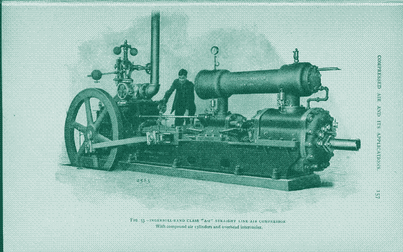
Starting in the 1860s and continuing into the 1900s, compressed air (or “pneumatics”) was at the centre of another technological revolution. This time, pneumatics established itself as the most versatile and widely used power transmission technology before the introduction of electricity. 12
Because electric power was still distributed at low voltages (“hydraulics”) had better transmission efficiencies over longer distances. However, compressed air has a very practical advantage over water under pressure: air is available anywhere and its exhaust poses no problems, while hydraulic systems require a sufficient water supply as well as a means to drain the fluid after use.
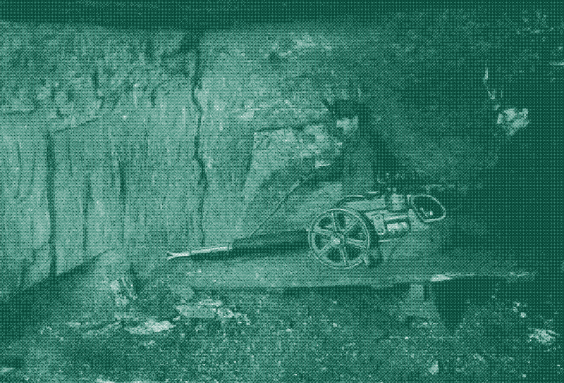
As a power transmission technology, compressed air was first applied in tunneling and mining. It provided an answer to the pressing need for a mechanical rock drill in the building of canals and railways, where tunnel construction formed a major bottleneck. Under severe hard-rock conditions, tunnel advance with hand drilling – using a pickaxe and explosives – was measured in inches per day, and tunnels of as little as half a mile in length could take years to complete. 12
In the new configuration, steam engines above-ground produced compressed air that was piped into the shafts or tunnels. The breakthrough of compressed air power transmission and pneumatic drilling tools happened with the digging of the 13.7 km long Mont Cenis tunnel in the Alps, which was completed in just 14 years (1857-1871). The technology quickly spread to the mining industry, especially in the US, where compressed air not only powered rock drills but also other machinery, such as hauling, pumping and stamping machines. 1213
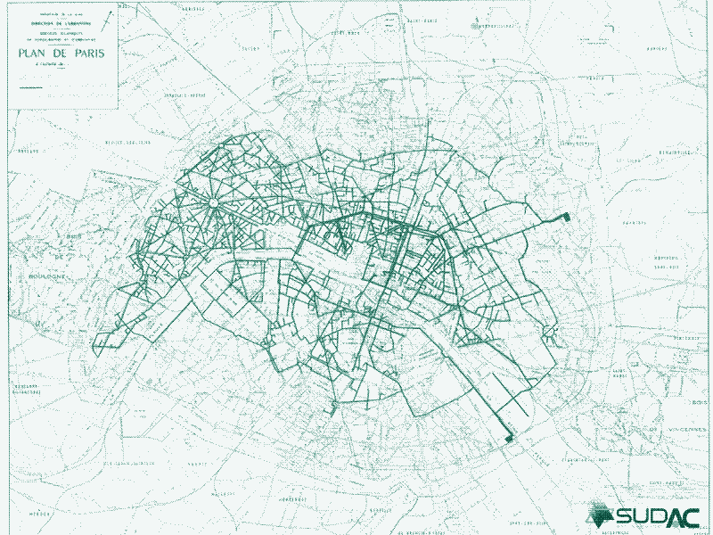
The Paris Compressed Air Network
With its effectiveness demonstrated so dramatically in power drilling, compressed air was adapted to a widening range of industrial operations: hammering, riveting, painting and spraying, pressure handling of fluids in processing, and a host of other uses. In the US, pneumatics came to be widely introduced as an auxiliary power system in manufacturing from the 1880s. The Census of 1900 referred to the widespread introduction of small pneumatic tools as possibly “the most important single tool development of the decade”. 12
Around the same time in Europe, the French took pneumatic power transmission one step further by setting up a city-wide power distribution network in Paris. It would remain in use for more than 100 years (from 1881 to 1994), distributing compressed air at a relatively low pressure of 5-6 bar over a network of (eventually) more than 900 km of mains, serving more than 10,000 customers. 1213
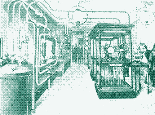
The Paris compressed air network started as a system designed exclusively for regulating clocks by impulses of compressed air sent through subterranean pipes. By 1889, the network in Paris was regulating 8,000 clocks through 65 km of mains. The clock regulating service was retired in 1927, after it became clear that electricity was better suited for the job. However, by that time, the compressed air network in Paris had proved highly successful in small industrial and service establishments. 12141516171813
The French set up a city-wide power distribution network in Paris, which served more than 10,000 customers and remained in use for 100 years
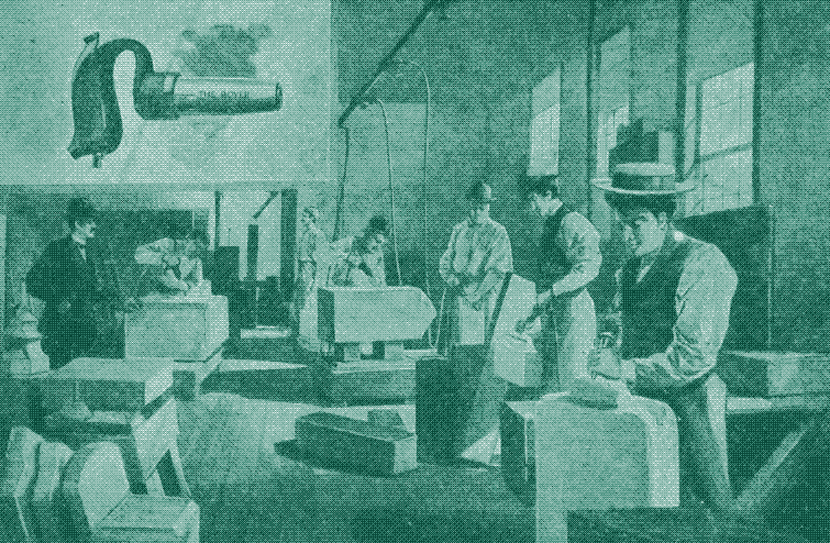
Already in 1892, F.E. Idell wrote that “among the smaller industrial purposes for which the air motors are used in Paris, I find the driving of lathes for metal and wood, of circular saws, drills, polishing machines, and many others. They are also used in the workshops of carpenters, joiners and cabinet-makers, of smiths, of umbrella makers, of collar-makers, of bookbinders, and naturally in a great many places where sewing machines are used, both by dressmakers, tailors, and shoemakers, from the smallest to the largest scale.” 13
Over the years, the share of commercial and domestic use of compressed air decreased, as electricity became more important. However, industrial consumption of compressed air kept growing, and many large factories in Paris – from car producers to glass manufacturers – were connected to the unique power distribution network until the very end. Dentists became new users during the 1970s and 1980s. 1213
First Lesson: Avoid Energy Conversions
What can be learned from comparing historical and current technologies based on compressed air? A first and crucial difference is the number of energy conversions involved. In historical systems, mechanical energy (for example, from a waterwheel or a steam engine) was directly converted to compressed air (using an air compressor), and then – most often – converted back to mechanical energy (for example, moving a pneumatic hammer). Consequently, there were only two sources of energy conversion loss: in the air compressor, and in the air expander.
Compressed air is still vital to the productivity of many industries and services around the globe, being used in thousands of applications – from food packaging and metal smelting to the manufacturing of microchips and plastics. However, compressed air is now produced by air compressors that run on electricity. This introduces two additional sources of energy loss: the electric generator (which converts mechanical energy from an energy source into electricity) and the electric motor (which converts electric energy back into mechanical energy to run the air compressor).
As a result, today’s industrial use of compressed air is very wasteful: assuming each converter is 75% efficient, and assuming no other energy losses, only 30% of the energy input is converted into useful output. 19
The overall system efficiency of the two existing CAES plants is even worse than that: not only is there the extra conversion step at the beginning of the chain (the energy loss in the windmill generator and in the electric motor running the compressor), but also at the end of the chain. This contrasts with industrial applications, where the end product is compressed air – a CAES plant converts the compressed air back into electricity.
When the efficiency of a CAES plant is said to be 40-50%, this only refers to the losses in the air compressor and the air expander (electric-to-electric efficiency). However, if we include the conversions to and from electricity, the overall system efficiency decreases to less than 20%, again assuming that each converter has an efficiency of 75%.
Now, imagine that a factory uses electricity from a CAES plant to power its industrial air compressors – a perfectly possible scenario. We then get the following energy conversion chain: mechanical energy is converted into electricity, electricity is converted into compressed air, compressed air is converted into electricity, electricity is converted into compressed air, and compressed air is converted in mechanical energy. That’s not two, or four, but six sources of energy conversion losses. Assuming each converter is 75% efficient, overall system efficiency now drops below 10%.
If we would connect a CAES plant directly to a factory that uses pneumatic tools, by piping compressed air from one to the other, there would be no need to convert compressed air into electricity and back.
On the other hand, if we would connect a CAES plant directly to a factory that uses pneumatic tools, by piping compressed air from one to the other, we would suffer just four sources of energy loss (generator, motor, compressor, expander). In the CAES plant, there is no longer a need to convert the stored compressed air back to electricity, while in the factory there is no need to compress the air a second time, using electricity. CAES and a factory could be up to 25 km apart – the distance up to which compressed air can be distributed efficiently.
The obvious next step is to compress the air in a CAES plant using a direct mechanical link between the wind mill and the air compressor, thus skipping the conversion from direct mechanical energy to electricity and back. Such an approach – which has been demonstrated on a small scale, in slightly different configurations 82021 – would make CAES entirely independent of electricity and would bring the energy conversion steps back to two, as in all historical systems. The only remaining energy conversion losses would be in the air compressor and in the air expander.
A rigid connection between windmill shaft and air compressor would also improve the efficiency of a CAES plant that is not connected to a factory but supplies electricity for general purposes, although the efficiency gain will be smaller. Obviously, compressing the air mechanically only works with windmills and not with solar PV panels, which do not produce mechanical energy.
Second Lesson: Use Heat and Cold for Other Purposes
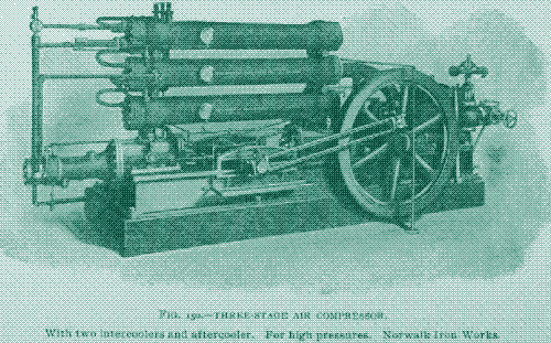
A second, related difference between present and historical uses of compressed air is how to deal with the temperature differences caused by compression and expansion of air. To improve efficiency, both CAES plants in operation use multiple air compressors. Multi-stage compression progressively increases the pressure and cools the air after each compression stage, using circulating water that is pumped to a cooling tower and released into the atmosphere. 22 23
Today, most CAES engineers are focused on further improving efficiency by using the waste heat of compression to reheat the compressed air upon expansion. This method is called “Advanced Adiabatic CAES” (AA-CAES) or “fuelless CAES” and removes the need to reheat with natural gas as in the standard “diabatic” CAES. The technology is expected to reach an overall efficiency of roughly 70%, bringing it closer to the efficiency of chemical batteries and pumped hydropower storage plants. 7
However, AA-CAES remains an unproven technology so far: a number of plants have been proposed, but none have yet made it past the design stage. 2223 The problem is twofold: first, the process enhancement increases the costs of a CAES plant by 20 to 40%; second, re-using the waste heat of the compression process is technologically challenging. To transfer heat at a high rate with a minimal temperature difference requires a very large surface area of contact. 7
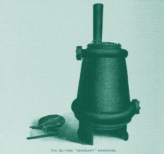
In the Paris compressed air power network, the cooling provided by the expansion of air was used for refrigeration, freezing, cooling and ventilation
If we look at older pneumatic systems, we see that there are other, easier ways to take advantage of temperature differences due to compression and expansion. In the Paris compressed air power network, engineers took advantage of the cooling that is provided by the expansion of air. In Paris, compressed air was usually heated by a coke fire before it was used by an air motor, increasing the power output in a way that is very similar to the use of natural gas in present-day CAES systems.
However, in bars and restaurants, these reheaters were not used. Instead, the cold air was used for refrigeration, freezing, cooling or ventilation purposes. In 1892, F.E. Idell described a Paris restaurant where “the exhaust was carried through a brick flue into the beer cellar. In this flue the carafes were set to freeze, and large moulds of block ice were also being made for table use, while the air was still cold enough in passing away through the beer cellar to render the use of ice for cooling quite unnecessary, even in the hottest weather.” 13
The use of compressed air for cooling or freezing sometimes went together with the production of electricity for lighting, driving a dynamo. In these cases, the air motors were basically worked for their exhaust, with electric light being the by-product. Taking advantage of temperature differences also happened in the earlier mining applications, where the exhaust of the rock drills helped to cool (and ventilate) the mines.
A similar and promising idea today, is compressed air energy storage combined with thermal storage to provide electricity, heating, cooling, refrigeration and/or ventilation at the same time. In fact, this approach also avoids several energy conversions, as it could replace refrigerators, freezers, air-conditioners and heating systems running on electricity. The method could work at the level of a city district or an industrial area 23, but it is especially interesting for decentralised energy storage using aboveground storage containers
As we have seen, a higher air pressure can greatly reduce the size of a compressed air storage vessel, but only at the expense of increased waste heat. In individual buildings, space for storage vessels is limited, while there is a large demand for heat and cold, as well as electricity. Increasing the air pressure makes the storage vessel smaller and increases the production of heat and cold, meeting all energy needs of a household.
Some proposed designs follow other approaches to deal with the heat of compression, and these could work for both large-scale and small-scale CAES systems. One interesting idea is a compressed air energy storage system that runs on wind energy as well as solar energy. 24 Wind energy is stored in the form of compressed air by compressor chain, as in the other CAES plants. However, solar energy from a parabolic dish is stored in an insulated solar thermal tank and used to reheat the compressed air prior to expansion. Because the heat from the compression process is no longer needed to warm the air upon expansion, it is used to produce hot water.
A similar concept for a hybrid thermal and compressed air energy storage design uses electric heating instead of solar thermal power. 25 Because the workload in these systems is shifted from pure conversion to investing partially in thermal storage, energy densities well in excess of traditional CAES can be achieved, and the size of the air storage can be reduced.
Third Lesson: Improve the Air Compressor
A third way to improve the efficiency of compressed air energy storage is by using more energy efficient air compressors and expanders. This strategy is opposite to the one we explained before. Instead of taking advantage of heat and cold to make the system more efficient, it tries to minimize waste heat production during compression (and, consequently, to limit cooling during expansion).
Once again, it pays to look to the past for inspiration. Surprisingly, the holy grail of “isothermal” air compression – in which no waste heat is produced at all – was found at least 400 years ago. The hydraulic air compressor – or “trompe”, as it was originally known – was an Italian invention first mentioned by name in 1588, but possibly already known in Antiquity.
From the 1600s onwards, dozens of “trompes” furnished a continuous air blast to early iron and brass-smelting furnaces in the French/Spanish Pyrenees. 2627 Compared to a waterwheel running a wooden piston compressor, it was roughly three times more efficient, allowing higher iron production with less water power resources.
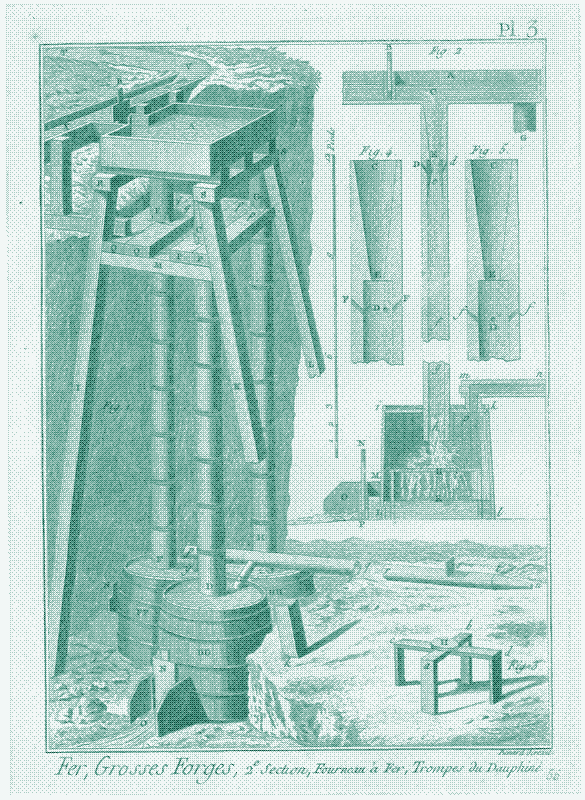
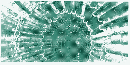
The trompe consisted of one or more vertical wooden tubes through which water was channeled by gravity. Upon its descent, the water absorbed air through holes in the tube and acted as a continuous piston in compressing the air. At the bottom of the tube, the air was separated from the water in a receptacle, after which it was sent to the furnace nozzle by adjustable pressure. Remarkably, the hydraulic air compressor produced compressed air without any moving parts, other than gate valves to shut off incoming water flow. This made it an extremely reliable device. 2628
The hydraulic air compressor produced compressed air without any moving parts, which made it an extremely reliable and efficient device
In the 19th century, the design of the hydraulic air compressor was further improved, making it more efficient and practical. In 1861, a hydraulic air compressor was built to power the rock drills for the construction of the Mont Cenis tunnel in the Alps, but the technology reached its heydays only at the end of the nineteenth century, this time in the mining industry.
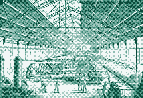
Over a 33-year period starting in 1896, eighteen gigantic hydraulic air compressors were built, mostly in the US, Canada, Germany and Sweden. In the largest of these installations, which were partly or completely built underground, water and air fell through pipes and shafts – hewn out of the rocks – which could be more than 100 metres deep and up to 4 metres wide. The delivery pressure amounted to 8 bar and the power output could reach 3,000 kilowatts. 2930
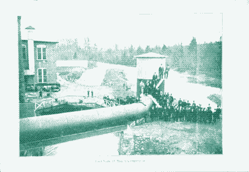
The first installations used a multitude of small downward air pipes, as in the original trompe, while later installations would use only two shafts. Leets and penstocks delivered water to air-water ‘mixing heads’ of various designs, and the compressed air was often subdivided to reach different mines and piped over distances of many kilometres. Most hydraulic air compressors operated for decades, the last one until 1981. 29 30
Performance tests, periodically carried out between the 1890s and 1950s, report that the hydropower-to-pneumatic power conversion efficiency ranged between 53% and 88%. More recent research has lowered these numbers to account for gas solubility effects, reporting efficiencies of 40 to 78%. 2928 Although hydraulic air compression produces little waste heat, a new type of energy loss is introduced: some of the air dissolves in the water and thus bypasses the air-water separation process, reducing the mass flow of air at outlet. 29
The hydraulic air compressor has seen renewed interest lately. A Canadian research team developed a 30-m tall hydraulic air compressor demonstrator rig in a former mine elevator shaft. 2931 The “HAC Demonstrator Project” measures and verifies the energy savings potential of the technology primarily for deep mining applications. However, it could also be an alternative for multi-stage compressors used in industry and in CAES systems. This is because the new design can also be set up in closed-loop configuration, using a pump instead of a natural head of water.
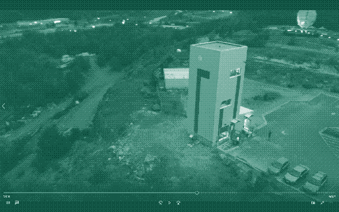
Although the pump introduces extra energy use, a closed-loop configuration has two important advantages. First, it could be applied anywhere, rather than just in proximity to an exploitable water source and a large height difference. Second, it offers the opportunity to suppress the undesirable effects of solubility physics, for example through the addition of salt to the circulating water.
According to the researchers, a closed-loop hydraulic air compressor could have an efficiency of 75%, taking into account the extra energy use from the pump. This is 13% more efficient than a three-stage centrifugal compressor, and cost advantages will be larger because of lower maintenance requirements. 2931
The hydraulic air compressor seems like a perfect match for large-scale CAES systems with underground reservoirs. In fact, many of the 19th and 20th century hydraulic air compressors used the lower air separator chamber also for compressed air energy storage, in what could be considered the first large-scale use of CAES. The storage – which could be as large as 5,600 m3 – was used to meet a short-time excess demand for air, meaning that the hydraulic air compressor did not have to be designed for the largest loads. 28
The Future of Compressed Air
None of these ideas will make CAES plants 100% energy efficient. However, they could help make them reach similar efficiencies to batteries, but with much lower environmental issues and much less energy invested. In the next article, we focus in more detail on small-scale CAES systems, which promise to be a sustainable alternative to chemical batteries in off-the-grid systems
Thanks to George Fleming.
Reactions
To make a comment, please send an e-mail to solar (at) lowtechmagazine (dot) com. Your e-mail address is not used for other purposes, and will be deleted after the comment is published. If you don’t want your real name to be published, sign the e-mail with the name you want to appear.
Reactions
akb
Fascinating history, thanks. I came across two incarnations of the trompe idea on Youtube that might be of interest.
The first was what the author describes as a hybrid of a trompe and a water ram. He used a small stream and 8’ of head to accumulate air in a PVC pressure vessel to 60psi.
https://www.youtube.com/watch?v=8wX4WtOHFZE
The 2nd was of a guy who got a grant from US DOI to use a trompe to help cleanup iron polluted water at an old mining site. The compressed air aids in oxidizing the iron to cause it to settle out.
https://www.youtube.com/watch?v=I85esMMoRa4
Tyler August
Dr. Millar’s HAC Demonstrator is installed in the Big Nickel Mine at Dynamic Earth, a geology-based science centre in Sudbury, Ontario, Canada. Part of the agreement with the science center is that the public has access to view the experimental facility and ask questions of the researchers.
Research is ongoing, so if you’re ever in the area, it’s worth checking out. One thing they are currently exploring is adding various salts to the water at the HAC demonstrator to reduce gas solubility and increase efficiency even further.
kris de decker
@ bobby mobby
That makes sense and we actually built it for the human power plant: https://krisdedecker.typepad.com/.a/6a00e0099229e8883301bb09c3cf1d970d-pi
The image shows the hand powered version, but later we converted it to pedal power. More here: https://www.humanpowerplant.be/human_power_plant/prototype-human-power-plant.html
We used a very old compressor and both the hand and foot powered drive were very crude. And yet, it worked very well. It would work even better using the machines that you link to (and thanks for that!).
John Davies
Locomotives running on compressed air have a long history - http://www.douglas-self.com/MUSEUM/LOCOLOCO/airloco/airloco.htm.
Often used for short distances where range wasn’t a problem, e.g. shunting, or for environments where a steam engine was hazardous, e.g. underground.
Logan Simmering
“Obviously, compressing the air mechanically only works with windmills and not with solar PV panels, which do not produce mechanical energy”
Solar thermal systems could be used to produce mechanical energy, as seen here
https://www.youtube.com/watch?v=iSoXWt4hBpc
nomadic
Couldn’t return air shafts provide wind tunnels to exploit the air for power?
Charles R. Patton
Mentioned in article:
“Once again, it pays to look to the past for inspiration. Surprisingly, the holy grail of “isothermal” air compression – in which no waste heat is produced at all – was found at least 400 years ago. The hydraulic air compressor – or “trompe”, as it was originally known – was an Italian invention first mentioned by name in 1588, but possibly already known in Antiquity.”
A very old 7th century as referenced in:
https://books.google.com/books?id=bV9WPMQoizkC&pg=PA189&lpg=PA189&dq=history+of+herreria+de+compludo&source=bl&ots=RuNX26BSCQ&sig=ACfU3U0d86uTYQVLgsb9gf0GbN62q0eACQ&hl=en&sa=X&ved=2ahUKEwivtNfy283mAhXxIjQIHal9ARsQ6AEwFXoECB8QAQ#v=onepage&q=history%20of%20herreria%20de%20compludo&f=false
Roman forge, the “herreria de compludo” in Spain uses (it has been restored) a trompe for pressured air to run the “blast” furnace and various forge charcoal beds around the water wheel powered forge hammers. So it appears that the trompe concept existed at least 1300 years ago. As it was Roman, the concept may have been passed down through the generations as it is very simple and reliable with a good supply of water.
bobby mobby
Hi again,
I was thinking something like:
https://www.gunt.de/fr/produits/modele-en-coupe-compresseur-a-piston/051.14010/mt140-10/glct-1:pa-149:pr-983
or
https://www.jinbomarine.com/marine-manually-operated-portable-emergency-hand-operated-air-compressor.html
What do you guys think?
Would that make sense to couple this with a CAES multi-bottleoff-grid system & to decharge to create electricity or use it with tools?
Cheers!
Kris De Decker
@ bobby mobby
That makes sense and we actually built it for the human power plant: https://krisdedecker.typepad.com/.a/6a00e0099229e8883301bb09c3cf1d970d-pi
The image shows the hand powered version, but later we converted it to pedal power. More here: https://www.humanpowerplant.be/human_power_plant/prototype-human-power-plant.html
We used a very old compressor and both the hand and foot powered drive were very crude. And yet, it worked very well. It would work even better using the machines that you link to (and thanks for that!).
Brian White
What about very low pressure air production and usage? I made mini trompes directly powering airlift pumps on a stream in Ireland starting around 1987 and one worked for about 15 years. I have a youtube video about it, “world’s simplest pump”. It used 200 to 300 liters per minute of water falling half a meter as its power and it pumped water to sheep at, I think, 5 meters above the stream and to cattle at 3.5 meters above the stream. Pumping in the airlift pump was by plug flow directly up and by slug flow on an incline. Since 2013 in Canada, I have used a mains powered pond air pump to power mini airlift pumps that cycle water in my garden planters and greenhouse. They use 1 meter water pressure or less (1.5 psi or less) on my “low power pneumatic grid. It currently runs 9 air lift pumps, in 2 greenhouses and a couple of planters. I also used it to run nft hydroponics over 2 summers.